

Synchronous Machine Model
This page documents the mathematical model of the synchronous machine implemented in RAMSES. The model is a detailed sixth-order model, including four rotor windings with saturation effects. It uses the Equal-Mutual-Flux-Linkage (EMFL) per unit system and supports detailed (round rotor, salient-pole) and simplified (field winding only) configurations through model switches.
Model Switches
Section titled “Model Switches”To accommodate different rotor configurations within a single model, integer “model switches” are defined:
| Switch | Meaning |
|---|---|
| 1 if there is a damper winding , 0 otherwise | |
| 1 if there is a damper winding , 0 otherwise | |
| 1 if there is an equivalent winding , 0 otherwise |
| Model | Switches |
|---|---|
| Detailed, round rotor | |
| Detailed, salient-pole rotor | |
| Detailed, salient-pole rotor | |
| Simplified, field winding only |
The second and third combinations yield the same results. Models with fewer rotor windings are specified by skipping the corresponding data in the SYNC_MACH record (see below).
Park Transformation
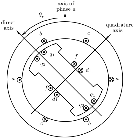
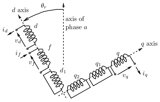
Section titled “Park Transformation”The well-known Park transformation is used to replace time-varying inductances and oscillatory stator currents and voltages with constant values. The machine is represented by equivalent windings along the direct () and quadrature () axes: a field winding and damper winding on the axis, and windings , on the axis:
Flux-Current Relationships
Section titled “Flux-Current Relationships”Using the EMFL per unit system, the relationship between magnetic flux linkages and currents is:
The and components of the air-gap flux are:
Individual flux linkages in terms of air-gap flux:
Rotor currents from flux linkages:
Saturation Model
Section titled “Saturation Model”Let and be the unsaturated direct- and quadrature-axis mutual inductances. The saturated values and are:
where and are the saturation exponents specified in the SYNC_MACH record.
Substituting into the air-gap flux expressions yields the algebraic equations:
Reference Frame
Section titled “Reference Frame”All synchronous machines have their rotor positions referred to the axis of the network reference frame (see Reference Frames & Initialization). The rotor angle of a machine is the angle difference between its axis and the reference axis. In steady state, the machine internal emf (proportional to field current) is aligned along the axis; is thus the phase angle of that emf with respect to the axis.
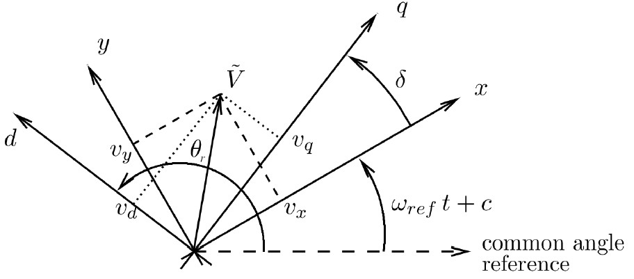
The and components of the stator voltage and current relate to the network components through the rotor angle :
After transformation, the air-gap flux algebraic equations in coordinates become:
Park Equations
Section titled “Park Equations”Original form
Section titled “Original form”where is the stator (armature) resistance, the field winding resistance, , , the rotor winding resistances, the rotor speed (pu), the nominal angular frequency (rad/s), the field voltage, and a coefficient to pass from per unit values of the excitation system to per unit values of the machine.
The stator equations are transformed to the frame using the rotation matrices above, and the rotor currents are eliminated using the flux-current relationships, yielding the equations actually solved by RAMSES:
Stator equations (algebraic, in - frame)
Section titled “Stator equations (algebraic, in xxx-yyy frame)”Rotor equations (differential)
Section titled “Rotor equations (differential)”Rotor Motion
Section titled “Rotor Motion”where is the inertia constant (in s), the mechanical torque produced by the turbine, a coefficient to pass from per unit values of the turbine to per unit values of the machine, and the angular speed of the reference axes: in the COI reference frame, or 1 pu in the synchronous frame (selected by the $OMEGA_REF solver setting).
The electromagnetic torque is:
State Variables and Equations Summary
Section titled “State Variables and Equations Summary”The model has 10 state variables: , , , , , , , , , .
These are balanced by:
- 4 algebraic equations: air-gap flux (d and q), stator voltage (d and q)
- 6 differential equations: field flux, d1 damper flux, q1 damper flux, q2 damper flux, rotor angle, rotor speed
Per Unit System and IBRATIO
Section titled “Per Unit System and IBRATIO”The synchronous machine model uses the EMFL per unit system, while the excitation system typically uses its own per unit system. The parameter IBRATIO bridges these two bases:
where is the field winding base current in the machine model and is the base current in the excitation system model. The relationship between per-unit field currents in the two systems is:
Common per unit conventions for IBRATIO
Section titled “Common per unit conventions for IBRATIO”Open-circuit unsaturated machine (most common): is the field current that produces nominal stator voltage ( pu) at nominal speed ( pu) with the stator open, neglecting saturation:
Open-circuit saturated machine: Same conditions but with saturation:
Saturated machine at nominal operating conditions: is the field current when the machine produces nominal active and reactive powers (, ) at nominal voltage and speed, with saturation.
SYNC_MACH Record
Section titled “SYNC_MACH Record”The machine model requires the nominal system frequency, given by the mandatory FNOM record (see Solver Settings):
FNOM F ;where F is the nominal frequency in Hz.
The synchronous machine itself is declared with the SYNC_MACH record:
SYNC_MACH name bus FP FQ P Q SNOM Pnom H D IBRATIO TYPE_MOD <14 machine parameters, see below> EXC exc_type param1 param2 ... TOR tor_type param1 param2 ... ;TYPE_MOD is a keyword selecting which of two equivalent parameter formats
the 14 machine parameters that follow are given in:
-
RL: the inductances and resistances of the Park model are supplied directly:RL Ll Mdu Llf Lld1 Mqu Llq1 Llq2 m n Ra Rf Rd1 Rq1 Rq2 -
XT: characteristic reactances and open-circuit time constants are supplied; RAMSES converts them internally to the Park parameters (see Parameter Conversion):XT Xl Xd X'd X"d Xq X'q X"q m n Ra T'do T"do T'qo T"qo
Common parameters
Section titled “Common parameters”| Parameter | Description | Unit |
|---|---|---|
name | Machine name (max 20 characters) | |
bus | Connection bus name (max 8 characters) | |
FP | Active power participation fraction (0–1) | |
FQ | Reactive power participation fraction (0–1) | |
P | Initial active power (used when FP = 0) | MW |
Q | Initial reactive power (used when FQ = 0) | Mvar |
SNOM | Nominal apparent power, used as base power in the machine model | MVA |
Pnom | Nominal active power of the turbine, used as base power for the turbine model | MW |
H | Inertia constant | s |
D | Damping coefficient (usually set to zero when the damper windings are modelled) | pu |
IBRATIO | Field current base ratio (see above) | pu |
TYPE_MOD | Parameter format keyword: RL or XT (case-insensitive) |
Machine parameters, XT format
Section titled “Machine parameters, XT format”| Parameter | Description | Unit |
|---|---|---|
Xl | Leakage reactance | pu |
Xd | d-axis synchronous reactance () | pu |
X'd | d-axis transient reactance (must be smaller than Xd) | pu |
X"d | d-axis subtransient reactance (* if no damper winding) | pu |
Xq | q-axis synchronous reactance () | pu |
X'q | q-axis transient reactance (* if no winding; must be smaller than Xq) | pu |
X"q | q-axis subtransient reactance (* if no winding) | pu |
m | Saturation coefficient (set to 0 to neglect saturation) | |
n | Saturation exponent (ignored when m = 0) | |
Ra | Armature resistance | pu |
T'do | d-axis open-circuit transient time constant | s |
T"do | d-axis open-circuit subtransient time constant (* if no damper winding) | s |
T'qo | q-axis open-circuit transient time constant (* if no winding) | s |
T"qo | q-axis open-circuit subtransient time constant (* if no winding) | s |
Machine parameters, RL format
Section titled “Machine parameters, RL format”| Parameter | Description | Unit |
|---|---|---|
Ll | Stator leakage inductance | pu |
Mdu | Unsaturated d-axis mutual inductance | pu |
Llf | Field winding leakage inductance | pu |
Lld1 | damper leakage inductance (* if no winding) | pu |
Mqu | Unsaturated q-axis mutual inductance | pu |
Llq1 | winding leakage inductance (* if no winding) | pu |
Llq2 | winding leakage inductance (* if no winding) | pu |
m | Saturation coefficient (set to 0 to neglect saturation) | |
n | Saturation exponent (ignored when m = 0) | |
Ra | Armature resistance | pu |
Rf | Field winding resistance | pu |
Rd1 | damper resistance (* if no winding) | pu |
Rq1 | winding resistance (* if no winding) | pu |
Rq2 | winding resistance (* if no winding) | pu |
Omitting rotor circuits
Section titled “Omitting rotor circuits”A rotor circuit the machine does not have is skipped by putting * in both
of its fields, the inductance/reactance and the matching
resistance/time-constant field (specifying only one is an error):
| Circuit | RL fields | XT fields | Model switch set to 0 |
|---|---|---|---|
| damper | Lld1, Rd1 | X"d, T"do | |
| winding | Llq1, Rq1 | X'q, T'qo | |
| winding | Llq2, Rq2 | X"q, T"qo |
The combination with (field winding plus
both q-axis windings but no d-axis damper) is rejected. In the XT format,
if the fitted Park parameters come out negative, RAMSES logs an
“unrealistic Park inductances or resistances” warning: the supplied
reactances and time constants are physically inconsistent.
All reactances, inductances and resistances are in per unit on the machine base (, nominal voltage), using the EMFL per unit system for the rotor quantities. Time constants are entered in seconds and normalised internally by .
The EXC and TOR sub-records specify the excitation system and turbine-governor models. See the Model Reference for available models.
Initialization Output
Section titled “Initialization Output”At initialization RAMSES prints one block per synchronous machine. Example:
NUMBER OF SYNCHRONOUS MACHINES :    1
machine              at bus                 V            P           Q        delta    sat    island  br                     excit model          vf(pu)   torque model               Tm(pu)
G5                   5                    1.0000    450.00186     68.49769    70.99   1.0000       1    1                     exc_GENERIC          2.3680   THERMAL_GENERIC1          0.97826
Here the machine G5, connected to bus 5, is in service (br = 1) and injects about 450 MW and 68 Mvar into the grid under a bus voltage of 1 pu.
deltais the initial value of the rotor angle , in degrees.satis the saturation factor the ratio between the field current in the saturated machine and the corresponding field current when saturation is neglected, for the same operating conditions. It characterizes the extra excitation current needed in the presence of saturated material ( whenmis set to zero).vfis the initial field voltage on the exciter base, which is indirectly defined by theIBRATIOparameter of the machine.Tmis the initial mechanical torque on the turbine base, which is defined by thePnomparameter of the machine.
Parameter Conversion (XT ↔ RL)
Section titled “Parameter Conversion (XT ↔ RL)”For a detailed derivation of how STEPSS converts the XT standard parameters
(reactances and open-circuit time constants) to the RL Park parameters
(inductances and resistances), including the exact algorithm from the source,
known conversion pitfalls when cross-checking against EMT simulators, and a
reference Python implementation, see: