

Custom Governor Models
This page documents the custom turbine-governor (tor_) models in RAMSES. These models are implemented in Fortran using the legacy multi-subroutine API and cover a wide range of prime-mover types: thermal (steam), gas turbine, hydraulic, nuclear, and simplified equivalents.
CONSTANT (tor_constant)
Section titled “CONSTANT (tor_constant)”The data-file model name is CONSTANT.
Scientific Description
Section titled “Scientific Description”The tor_constant model provides a constant mechanical torque source. The mechanical torque is fixed at its initialisation value and does not respond to speed deviations or load changes:
The single algebraic state satisfies:
The observable output is mechanical power:
Implementation details:
nbxvar = 1,nbzvar = 0,nbdata = 0- One additional parameter:
prm(1) = Tm0(set at initialisation from load-flow) - Observable:
Pm = x(1) * omega
Parameters
Section titled “Parameters”| Parameter | Description |
|---|---|
| (none) | No user-supplied parameters. is taken from the load-flow initialisation. |
Usage Example
Section titled “Usage Example”SYNC_MACH g6 g6 1. 1. 0. 0. 400. 360. 6. 0. 2.05 XT 0.15 2.2 0.3 0.2 2. 0.4 0.2 0.1 6.0257 0. 7.00 0.05 1.5 0.05 EXC GENERIC1 3.0618 -0.1 1. 0. 100. -1. -20.0 10. 120. 5. 12.5 0.1 0. 5. 1 75. 15. 0.22 0.012 0.22 0.012 -0.1 0.1 TOR CONSTANT ;- Useful for machines operating at fixed setpoint, for testing generator models in isolation, or as a placeholder.
- The mechanical power observable will vary slightly with speed changes.
TOR CONSTANTtakes no parameters, is set automatically from the load-flow initialisation.
1ST_ORDER (tor_1storder)
Section titled “1ST_ORDER (tor_1storder)”The data-file model name is 1ST_ORDER (uppercase, with the underscore).
Scientific Description
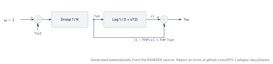
Section titled “Scientific Description”The tor_1storder model is a first-order speed governor with droop and a two-mass (HP/LP) turbine representation. It captures the primary frequency response through a proportional-droop speed controller with a first-order lag.
Speed controller with droop :
The mechanical torque setpoint is:
The HP torque tracks through a first-order lag with time constant :
The LP (shaft) torque is a weighted combination:
where is the fraction of power generated in the HP stage.
From the Fortran equations:
f(1) = (-x(1) + (prm(4) - (omega-1.d0)/prm(3))) / prm(2)f(2) = (1.d0-prm(1))*x(1) + prm(1)*(prm(4)-(omega-1.d0)/prm(3)) - x(2)i.e.:
prm(1) = FHP(HP fraction),prm(2) = T2(time constant),prm(3) = R(droop)prm(4) = Tm0(setpoint, set at init)
Implementation details:
nbxvar = 2,nbzvar = 0,nbdata = 3- State 1 = HP torque
x(1), State 2 = LP torquex(2) - Observables:
HP torque,LP torque
Parameters
Section titled “Parameters”| Parameter | Description |
|---|---|
FHP | Fraction of torque produced by the HP turbine stage (0–1) |
T2 | Governor/HP turbine time constant (s) |
R | Speed droop (pu/pu) |
Usage Example
Section titled “Usage Example”SYNC_MACH g1 g1 1. 1. 0. 0. 800. 760. 3. 0. 0.95 XT 0.15 1.1 0.25 0.2 0.7 * 0.2 0.1 6.0257 0. 5.00 0.05 * 0.1 EXC GENERIC1 1.8991 -0.1 0. 1. 100. -1. -11 10. 70. 10. 20. 0.1 0. 4. 1 75. 15. 0.2 0.01 0.2 0.01 -0.1 0.1 TOR 1ST_ORDER 0.30 0.50 0.05 ; ! FHP T2 RFHP = 0makes the model a pure first-order lag on the total torque.FHP = 1bypasses the HP lag entirely; the torque instantly tracks the droop setpoint.- Typical primary-frequency response studies use
R = 0.04–0.05.
THERMAL_GENERIC1 (tor_thermal_generic1)
Section titled “THERMAL_GENERIC1 (tor_thermal_generic1)”The data-file model name is THERMAL_GENERIC1.
Scientific Description
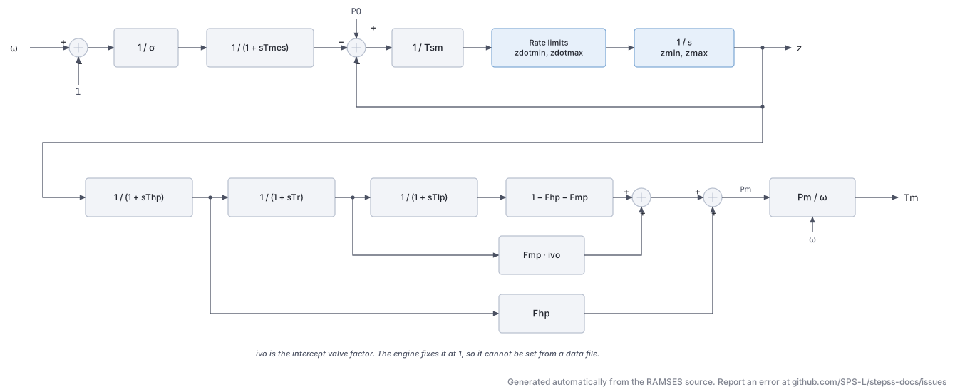
Section titled “Scientific Description”The tor_thermal_generic1 model is a generic multi-stage steam turbine governor, suitable for both single-shaft and cross-compound units. It includes a speed controller with rate-limiting, a three-section steam chest/reheater, and separate HP, MP, and LP turbine stages.
Speed governor:
The speed deviation is divided by the droop and measured with time constant :
The gate demand is what remains of the power setpoint after that term and the current gate position are taken off:
It is divided by the servo time constant , rate-limited to , and integrated into the gate opening within .
Turbine power stages:
The gate opening drives three lags in series, the reheat stage carrying the intercept valve factor :
Each stage contributes its own fraction of the power, and the three fractions sum to one:
Total mechanical power, and the torque delivered to the shaft:
Parameters:
| Parameter | Index | Description |
|---|---|---|
sigma | 1 | Speed droop (pu/pu) |
Tmes | 2 | Speed measurement time constant (s) |
Tsm | 3 | Servo/gate time constant (s) |
zdotmin | 4 | Minimum gate rate (pu/s) |
zdotmax | 5 | Maximum gate rate (pu/s) |
zmin | 6 | Minimum gate opening (pu) |
zmax | 7 | Maximum gate opening (pu) |
Thp | 8 | HP turbine time constant (s) |
Fhp | 9 | HP power fraction |
Tr | 10 | Reheater / MP time constant (s) |
Fmp | 11 | MP power fraction |
Tlp | 12 | LP turbine time constant (s) |
Implementation details:
nbxvar = 10,nbzvar = 2,nbdata = 12,nbaddpar = 2- Additional:
prm(13) = P0(initial power),prm(14) = ivo(intercept valve factor)
- Observables:
z,PmHP,PmMP,PmLP,Pm
Usage Example
Section titled “Usage Example”SYNC_MACH g1 g1 1. 1. 0. 0. 800. 760. 3. 0. 0.95 XT 0.15 1.1 0.25 0.2 0.7 * 0.2 0.1 6.0257 0. 5.00 0.05 * 0.1 EXC GENERIC1 1.8991 -0.1 0. 1. 100. -1. -11 10. 70. 10. 20. 0.1 0. 4. 1 75. 15. 0.2 0.01 0.2 0.01 -0.1 0.1 TOR THERMAL_GENERIC1 0.05 0.02 0.20 -0.10 0.10 0.0 1.05 0.30 0.30 7.0 0.40 0.50 ; ! sigma Tmes Tsm zdotmin zdotmax zmin zmax Thp Fhp Tr Fmp Tlp- The LP fraction is
1 - Fhp - Fmp; ensureFhp + Fmp ≤ 1. - Set
Tmes = 0to bypass the speed measurement filter (instantaneous speed sensing). - Rate limits
zdotmin/zdotmaxare critical for AGC studies.
HYDRO_GENERIC1 (tor_hydro_generic1)
Section titled “HYDRO_GENERIC1 (tor_hydro_generic1)”The data-file model name is HYDRO_GENERIC1.
Scientific Description
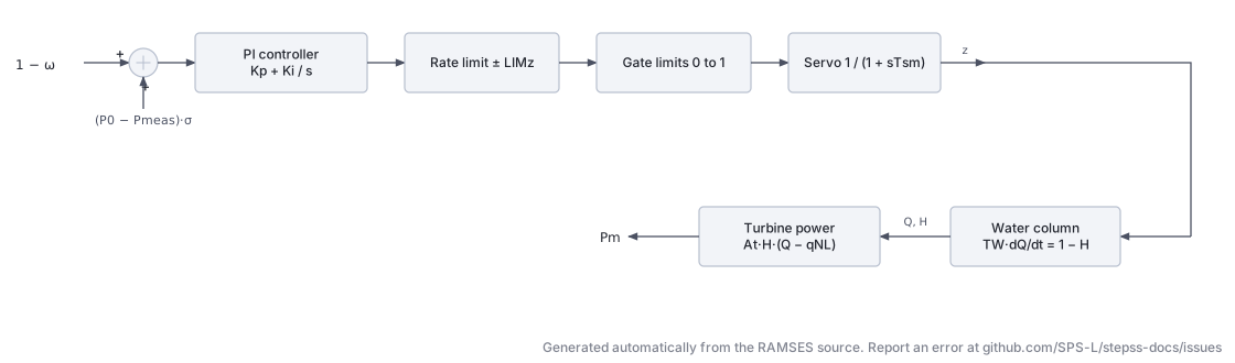
Section titled “Scientific Description”The tor_hydro_generic1 model is a generic hydraulic turbine governor with a penstock (water column) and PI controller. It implements the standard hydraulic governor structure following IEEE Std 1110 conventions.
PI speed governor:
The speed error with droop :
A PI controller with gains and drives the gate demand:
The gate is rate-limited by and position-limited by , with a servo time constant .
Water column (penstock):
The flow and head are related by the water-starting time :
The head is:
where is the no-load flow fraction.
Turbine mechanical torque:
Parameters:
| Parameter | Index | Description |
|---|---|---|
SIGMA | 1 | Speed droop (pu/pu) |
Tmes | 2 | Speed measurement time constant (s) |
Qv | 3 | No-load water flow fraction (pu) |
KP | 4 | PI proportional gain |
KI | 5 | PI integral gain |
TSM | 6 | Gate servo time constant (s) |
LIMZDOT | 7 | Gate velocity limit (pu/s) |
TW | 8 | Water starting time (s) |
Implementation details:
nbxvar = 6,nbzvar = 2,nbdata = 8,nbaddpar = 1- Additional:
prm(9) = P0(initial electrical power) - Observables:
z,Q,H,Pm
Usage Example
Section titled “Usage Example”SYNC_MACH g1 g1 1. 1. 0. 0. 800. 760. 3. 0. 0.95 XT 0.15 1.1 0.25 0.2 0.7 * 0.2 0.1 6.0257 0. 5.00 0.05 * 0.1 EXC GENERIC1 1.8991 -0.1 0. 1. 100. -1. -11 10. 70. 10. 20. 0.1 0. 4. 1 75. 15. 0.2 0.01 0.2 0.01 -0.1 0.1 TOR HYDRO_GENERIC1 0.04 2.0 0. 2.00 0.40 0.2 0.1 1.0 ; ! SIGMA TP Qv KP KI TSM LIMZDOT TWTW(water-starting time) is the most influential parameter; typical values are 0.5–3 s.- Increase
KP/KIcarefully: large values can cause governor instability with highTW. Qv = 0assumes no no-load losses.- Parameters follow the order in
dyn_A.txt:SIGMA TP Qv KP KI TSM LIMZDOT TW.
HYDRO_DG (tor_HYDRO_DG)
Section titled “HYDRO_DG (tor_HYDRO_DG)”The data-file model name is HYDRO_DG. Registered since 3.76.
Scientific Description
Section titled “Scientific Description”A hydraulic turbine governor for a dispersed generation unit that holds an active-power setpoint and does not provide primary frequency response.
The penstock and turbine are exactly those of HYDRO_GENERIC1.
What differs is the governor control law, and the difference is the point of the model.
HYDRO_GENERIC1 is a speed governor: its error signal carries an unconditional frequency
term, so the unit responds to system frequency whether or not that is wanted. HYDRO_DG
regulates power alone.
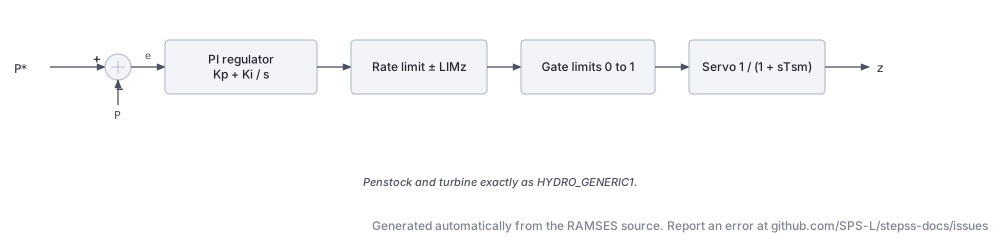
PI power regulator:
The error is the deviation from the setpoint captured at initialisation, with no droop term and no speed term:
There is no measurement lag on , so the regulator acts on the instantaneous electrical power. The gate follows through a servo of time constant , rate-limited to and position-limited to .
Water column and turbine, identical to HYDRO_GENERIC1:
Parameters:
| Parameter | Index | Description |
|---|---|---|
Qv | 1 | No-load water flow fraction (pu) |
Kp | 2 | PI proportional gain |
Ki | 3 | PI integral gain |
TSM | 4 | Gate servo time constant (s) |
LIMZDOT | 5 | Gate velocity limit (pu/s) |
TW | 6 | Water starting time (s) |
These are exactly parameters 3 to 8 of HYDRO_GENERIC1, in the same order. HYDRO_GENERIC1
precedes them with SIGMA (droop) and Tmes (speed measurement lag), and those two are what
HYDRO_DG does not have. Setting SIGMA to zero in HYDRO_GENERIC1 does not reproduce
HYDRO_DG, because the frequency term survives.
Implementation details:
nbxvar = 5,nbzvar = 2,nbdata = 6,nbaddpar = 1- Additional:
prm(7) = Pset, the initial electrical power, captured at initialisation - Observables:
z,Q,H,Pm,Pset
Usage Example
Section titled “Usage Example”SYNC_MACH G4 N4 1. 1. 0. 0. 5 4.5 3. 0. 1.9333 XT 0.0937 2.027 0.210 0.173 2.027 * 0.173 0.1 6 0.00 3.1 0.0387 * 0.0387 EXC AVR_DG 2.865 -0.1 0. 1. 100. -1. -20 10 50 4 20 0.1 0 5 1 0. 5. 1. 1. 1. 1. 0. 0. 0.04 0.06 -0.2 0.33 TOR HYDRO_DG 0.0 0.1 0.4 0.2 0.1 1.0 ; ! Qv Kp Ki TSM LIMZDOT TW- The setpoint is not a parameter.
Psetis captured from the power-flow solution at initialisation, so the unit holds whatever it was dispatched to. - Because there is no frequency term, a system built only of these units has no primary frequency control. That is deliberate for dispersed generation studies, and it is worth being explicit about when interpreting a frequency response.
Qv = 0assumes no no-load losses.- The head relation divides by the gate position, which is floored at 1e-3 in the implementation so a fully closed gate cannot produce a division by zero.
tor_gasturbm
Section titled “tor_gasturbm”Scientific Description
Section titled “Scientific Description”The tor_gasturbm model is a gas turbine governor following a multi-stage combustion model. It captures the compressor, fuel system, combustion chamber delay, and turbine torque characteristic. The name suffix m indicates a modified version.
Speed governor:
The governor error drives a PI controller producing a fuel demand signal. The speed governor uses:
with saturation limits .
Fuel system and combustion:
The fuel valve position g1 is driven through:
- A speed governor with gain and lead–lag time constants determined by ,
- A fuel flow path through first-order lag
- Combustion chamber lag
Turbine output:
The turbine mechanical power follows:
where is the combustion output through lag .
Additional thermodynamic correction terms involve (flame lag) and (exhaust correction ratio).
Parameters from Fortran source (prm array):
| Index | Name | Description |
|---|---|---|
| 1 | TDSP | Speed droop time constant (s) |
| 2 | STAT | Steady-state gain |
| 3 | ZZ | Governor proportional gain |
| 4 | XX | Lead numerator factor |
| 5 | YY | Lag denominator factor |
| 6 | SACC | Acceleration constant |
| 7 | MIN | Minimum fuel valve position (pu) |
| 8 | MAX | Maximum fuel valve position (pu) |
| 9 | TVALVE | Fuel valve time constant (s) |
| 10 | TGAZ | Combustion chamber time constant (s) |
| 11 | TF | Flame lag time constant (s) |
| 12 | ECR | Exhaust correction ratio |
| 13 | TCD | Compressor discharge time constant (s) |
| 14 | BF2 | Turbine power output slope |
| 15 | AF2 | Turbine power output intercept (pu) |
Implementation details:
nbxvar = 10,nbzvar = 4,nbdata = 15,nbaddpar = 1- Additional:
prm(16) = SETPOINT(initialised from load-flow power) - Observables:
g2,x4,g1
Usage Example
Section titled “Usage Example”SYNC_MACH g1 g1 1. 1. 0. 0. 800. 760. 3. 0. 0.95 XT 0.15 1.1 0.25 0.2 0.7 * 0.2 0.1 6.0257 0. 5.00 0.05 * 0.1 EXC GENERIC1 1.8991 -0.1 0. 1. 100. -1. -11 10. 70. 10. 20. 0.1 0. 4. 1 75. 15. 0.2 0.01 0.2 0.01 -0.1 0.1 TOR GASTURBM 0.05 1.0 25.0 0.50 1.0 1.0 0.0 1.0 0.05 0.40 0.01 0.0 0.20 1.0 0.0 ; ! TDSP STAT ZZ XX YY SACC MIN MAX TVALVE TGAZ TF ECR TCD BF2 AF2tor_govclasm
Section titled “tor_govclasm”Scientific Description
Section titled “Scientific Description”The tor_govclasm model is a classical thermal governor with a composite control law including deadband, droop, integral control, and combustion dynamics. The name stands for “governor classical model”.
Speed governor with deadband and droop:
The speed error passes through a deadband before entering a proportional–integral controller. The integral path has saturation at and gain . The reset time determines the integration rate.
Valve and combustion dynamics:
The valve demand passes through:
- A governor integrator with time constant , its rate held inside
- A first-order lag (valve actuator)
- A rate limiter (with gain ) representing fuel response
- A combustion/steam chest lag , producing fuel flow
- Lower bound:
- Transport delay (approximated)
- Turbine output through lag with limits
Parameters from Fortran source (prm array):
| Index | Name | Description |
|---|---|---|
| 1 | STAT | Governor static characteristic selector |
| 2 | DEADB | Deadband half-width (pu) |
| 3 | DBON | Deadband onset (pu) |
| 4 | TSM | Speed measurement / filter time constant (s) |
| 5 | V0 | Maximum valve opening rate, upper limit on the governor integrator rate (pu/s) |
| 6 | VFN | Minimum valve rate, applied directly as the lower bound, so normally negative (pu/s) |
| 7 | TFV | Valve actuator time constant (s) |
| 8 | VFR | Fuel flow rate limit (pu/s) |
| 9 | MAXINT | Maximum integral output (pu) |
| 10 | ALPHA | Integral controller gain |
| 11 | TRES | Integral reset time (s) |
| 12 | GOMP | Governor proportional gain |
| 13 | PVARMAX | Maximum power variation rate (pu) |
| 14 | PVARMIN | Minimum power variation rate (pu) |
| 15 | GPVAR | Power variation gain |
| 16 | KCR | Combustion gain |
| 17 | TCR | Combustion time constant (s) |
| 18 | MINFUEL | Minimum fuel flow (pu) |
| 19 | TDELAY | Combustion transport delay (s) |
| 20 | PMAX | Maximum turbine output (pu) |
| 21 | TCH | Steam chest / turbine lag (s) |
| 22 | PMIN | Minimum turbine output (pu) |
Implementation details:
nbxvar = 6,nbzvar = 10,nbdata = 22,nbaddpar = 1- Additional:
prm(23) = P0(initialised from load-flow power) - Observables:
x2,b3,b4
Usage Example
Section titled “Usage Example”SYNC_MACH g1 g1 1. 1. 0. 0. 800. 760. 3. 0. 0.95 XT 0.15 1.1 0.25 0.2 0.7 * 0.2 0.1 6.0257 0. 5.00 0.05 * 0.1 EXC GENERIC1 1.8991 -0.1 0. 1. 100. -1. -11 10. 70. 10. 20. 0.1 0. 4. 1 75. 15. 0.2 0.01 0.2 0.01 -0.1 0.1 TOR GOVCLASM 1.0 0.003 0.001 0.10 1.0 1.0 0.30 0.5 1.0 1.0 5.0 25.0 0.10 -0.10 0.05 1.0 0.20 0.05 0.30 1.05 0.30 0.05 ; ! STAT DEADB DBON TSM V0 VFN TFV VFR MAXINT ALPHA TRES GOMP PVARMAX PVARMIN GPVAR KCR TCR MINFUEL TDELAY PMAX TCH PMINtor_govhydr
Section titled “tor_govhydr”Scientific Description
Section titled “Scientific Description”The tor_govhydr model is a simplified hydraulic governor with PI control and a non-linear penstock. It differs from tor_hydro_generic1 in its simplified turbine characteristic and simpler water-column formulation.
PI governor:
where the speed error accounts for the droop and steady-state bias.
Penstock (two-lag water column):
The turbine mechanical power is computed via an empirical quadratic:
derived from the non-linear head-flow curve approximated at initialisation.
Parameters from Fortran source:
| Index | Name | Description |
|---|---|---|
| 1 | STAT | Steady-state gain selector |
| 2 | KP | Proportional gain |
| 3 | KI | Integral gain |
| 4 | TC | Governor/servo time constant (s) |
| 5 | V0 | Maximum gate opening rate, upper limit on gate velocity (pu/s) |
| 6 | VF | Maximum gate closing rate, entered as a positive magnitude and applied as (pu/s) |
| 7 | TCE2 | Second penstock time constant (s) |
| 8 | TCE1 | First penstock time constant (s) |
Implementation details:
nbxvar = 4,nbzvar = 4,nbdata = 8,nbaddpar = 1- Additional:
prm(9) = P0(initialised from load-flow power) - No observables defined (
nbobs = 0)
Usage Example
Section titled “Usage Example”SYNC_MACH g1 g1 1. 1. 0. 0. 800. 760. 3. 0. 0.95 XT 0.15 1.1 0.25 0.2 0.7 * 0.2 0.1 6.0257 0. 5.00 0.05 * 0.1 EXC GENERIC1 1.8991 -0.1 0. 1. 100. -1. -11 10. 70. 10. 20. 0.1 0. 4. 1 75. 15. 0.2 0.01 0.2 0.01 -0.1 0.1 TOR GOVHYDR 1.0 2.0 0.5 0.10 1.0 1.0 1.0 5.0 ; ! STAT KP KI TC V0 VF TCE2 TCE1TCE1corresponds roughly to the water-starting time .TCE2/TCE1sets the ratio of the two penstock lags.
tor_govnuc
Section titled “tor_govnuc”Scientific Description
Section titled “Scientific Description”The tor_govnuc model is a nuclear plant governor with deadband, droop, integral control, and a non-linear turbine characteristic via GOMP (the gain of the output multiplier). It is structurally similar to tor_govclasm but tailored for the slower, tightly-regulated dynamics of nuclear steam supply systems.
Speed governor:
The speed error passes through a deadband :
The error enters an integrator with rate limits (pu/s) filtered through a ramp time . The integrator output passes through a servo .
Turbine characteristic with GOMP:
The turbine output is non-linearly mapped through a gain :
where the limiter prevents over-power and is a piecewise-linear characteristic.
The steam-valve rate is held inside , then passes the valve actuator lag , the reset lag and to produce the final torque. overrides the rate during fast valving, a path the shipped model never takes: the code fixes its selector at 1 and leaves the fast-valving logic unwritten.
Parameters from Fortran source:
| Index | Name | Description |
|---|---|---|
| 1 | STAT | Governor static characteristic selector |
| 2 | DEADB | Deadband half-width (pu) |
| 3 | DBON | Deadband onset (pu) |
| 4 | GRADMAX | Maximum load gradient (pu/s) |
| 5 | GRADMIN | Minimum load gradient / unloading rate (pu/s) |
| 6 | TGRAD | Ramp filter time constant (s) |
| 7 | TSM | Servo time constant (s) |
| 8 | V0 | Maximum valve opening rate, upper limit on the steam-valve rate (pu/s) |
| 9 | VFN | Minimum valve rate, applied directly as the lower bound, so normally negative (pu/s) |
| 10 | TFV | Valve actuator time constant (s) |
| 11 | VFR | Valve rate limit (pu/s) |
| 12 | ALPHA | Integral gain |
| 13 | TRES | Reset time constant (s) |
| 14 | GOMP | Output power gain |
Implementation details:
nbxvar = 4,nbzvar = 8,nbdata = 14,nbaddpar = 1- Additional:
prm(15) = P0(initialised from load-flow power) - Observable:
TM
Usage Example
Section titled “Usage Example”SYNC_MACH g1 g1 1. 1. 0. 0. 800. 760. 3. 0. 0.95 XT 0.15 1.1 0.25 0.2 0.7 * 0.2 0.1 6.0257 0. 5.00 0.05 * 0.1 EXC GENERIC1 1.8991 -0.1 0. 1. 100. -1. -11 10. 70. 10. 20. 0.1 0. 4. 1 75. 15. 0.2 0.01 0.2 0.01 -0.1 0.1 TOR GOVNUC 1.0 0.005 0.002 0.02 -0.02 10.0 5.0 1.0 1.0 0.50 0.10 1.0 20.0 1.0 ; ! STAT DEADB DBON GRADMAX GRADMIN TGRAD TSM V0 VFN TFV VFR ALPHA TRES GOMP- Nuclear plants typically have slow load-following characteristics:
GRADMAXis typically 0.005–0.02 pu/s. - The
DEADBis important to prevent hunting around the setpoint. GOMPscales the turbine output; set to 1.0 for standard normalisation.