

IEEE Governor Models
This page documents the IEEE-standard turbine-governor models available in RAMSES, all using the tor_ prefix. These models implement standardised transfer-function blocks for diesel, gas-turbine, steam-turbine, hydraulic, and simplified ENTSO-E governors.
DEGOV1 (tor_DEGOV1)
Section titled “DEGOV1 (tor_DEGOV1)”Scientific Description
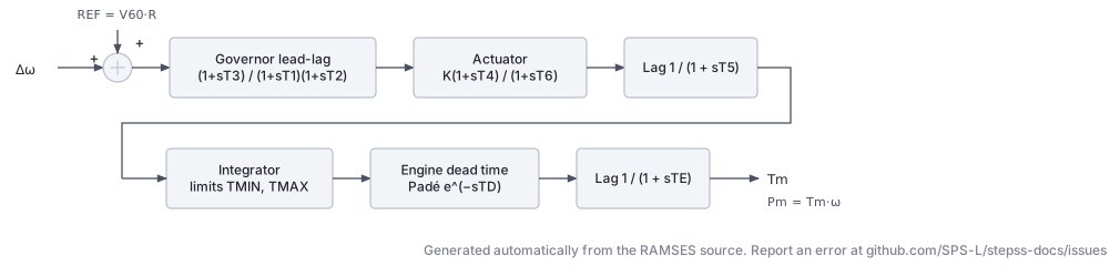
Section titled “Scientific Description”The DEGOV1 model represents the diesel engine governor as defined in the IEEE Committee Report on governors. It consists of three main stages:
1. Speed governor (electrical control / lead–lag)
The speed error is formed from the measured speed deviation and a reference signal derived from either mechanical power () or mechanical torque (), selected by the switch :
The governor speed error drives a second-order lead–lag controller (transfer function approximating a two-pole, two-zero system) with time constants , , :
2. Actuator (fuel injection system)
The governor output passes through a lead–lag block with gain and time constants , :
followed by a first-order lag , and an integrator with limits .
3. Engine dead time and torque output
The actuator output is subject to engine dead time , approximated by a second-order Padé:
The final mechanical torque is computed as:
The droop characteristic is:
Parameters
Section titled “Parameters”| Parameter | Description |
|---|---|
SWM | Input switch: 0 = mechanical torque (), 1 = electrical power () |
T1 | Governor time constant, lead numerator (s) |
T2 | Governor time constant, lag denominator (s) |
T3 | Governor time constant, second-order denominator (s) |
K | Actuator gain |
T4 | Actuator lead time constant (s) |
T5 | First-order actuator lag (s) |
T6 | Actuator lag time constant (s) |
TMIN | Minimum fuel/torque limit (pu) |
TMAX | Maximum fuel/torque limit (pu) |
TD | Engine dead time (s) |
R | Speed droop (pu/pu) |
TE | Engine time constant (s) |
Internal parameters: V60 (selected reference input, mechanical torque or electrical power according to SWM) and REF (V60 · R), both set at initialisation
Usage Example
Section titled “Usage Example”SYNC_MACH g1 g1 1. 1. 0. 0. 600. 570. 6. 0. 2.05 XT 0.15 2.2 0.3 0.2 2. 0.4 0.2 0.1 6.0257 0. 7.00 0.05 1.5 0.05 EXC GENERIC1 3.0618 -0.1 1. 0. 100. -1. -20.0 10. 120. 5. 12.5 0.1 0. 5. 1 75. 15. 0.22 0.012 0.22 0.012 -0.1 0.1 TOR DEGOV1 0 ! SWM: 0 = torque input, 1 = power input 0.02 ! T1: governor lead time constant (s) 0.02 ! T2: governor lag time constant (s) 0.20 ! T3: governor second-order denominator (s) 1.0 ! K: actuator gain 0.25 ! T4: actuator lead time constant (s) 0.009 ! T5: first-order actuator lag (s) 0.038 ! T6: actuator lag time constant (s) 0.0 ! TMIN: minimum fuel/torque limit (pu) 1.05 ! TMAX: maximum fuel/torque limit (pu) 0.01 ! TD: engine dead time (s) 0.05 ! R: speed droop (pu/pu) 0.05 ; ! TE: engine time constant (s)- Set
SWM = 0to use mechanical torque as the reference input,SWM = 1for electrical power. TMINandTMAXare per-unit limits on the integrator output (fuel demand / valve position).Ris the permanent droop; typical values are 0.04–0.05 pu/pu.- The Padé approximation of the dead time is a second-order filter.
- Parameters are listed in order:
SWM T1 T2 T3 K T4 T5 T6 TMIN TMAX TD R TE.
ENTSOE_simp (tor_ENTSOE_simp)
Section titled “ENTSOE_simp (tor_ENTSOE_simp)”Scientific Description
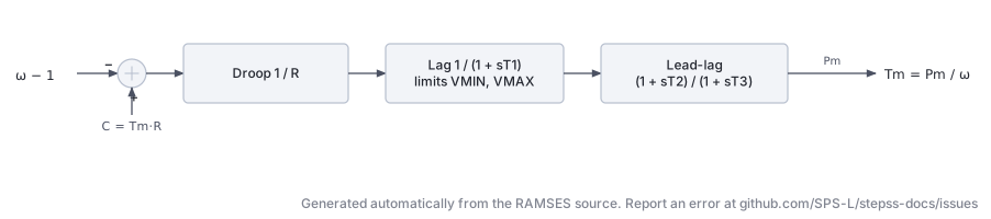
Section titled “Scientific Description”The ENTSOE_simp model is a simplified ENTSO-E speed governor suitable for primary frequency response studies. It is derived from the ENTSO-E recommendations for equivalent turbine-governor representation.
The governor equation forms a speed error with permanent droop :
This error drives a first-order lag (representing the valve or steam chest) with limits :
The turbine mechanical power is modelled by a lead–lag transfer function with time constants (zero) and (pole):
The final mechanical torque output accounting for shaft speed is:
Parameters
Section titled “Parameters”| Parameter | Description |
|---|---|
R | Permanent speed droop (pu/pu) |
T1 | Governor/valve time constant (s) |
VMIN | Minimum valve position / lower output limit (pu) |
VMAX | Maximum valve position / upper output limit (pu) |
T2 | Turbine lead time constant, zero (s) |
T3 | Turbine lag time constant, pole (s) |
Internal parameter: C = Tm · R (initialised from the load-flow mechanical torque)
Usage Example
Section titled “Usage Example”SYNC_MACH g1 g1 1. 1. 0. 0. 400. 360. 6. 0. 2.05 XT 0.15 2.2 0.3 0.2 2. 0.4 0.2 0.1 6.0257 0. 7.00 0.05 1.5 0.05 EXC GENERIC1 3.0618 -0.1 1. 0. 100. -1. -20.0 10. 120. 5. 12.5 0.1 0. 5. 1 75. 15. 0.22 0.012 0.22 0.012 -0.1 0.1 TOR ENTSOE_simp 0.05 ! R: permanent droop (pu/pu) 0.50 ! T1: governor/valve time constant (s) 0.0 ! VMIN: minimum valve position (pu) 1.1 ! VMAX: maximum valve position (pu) 0.0 ! T2: turbine lead time constant (s) 10.0 ; ! T3: turbine lag time constant (s)- Typical primary-frequency response studies use –.
- Setting simplifies the turbine to a pure first-order lag .
- This model is commonly used as a simplified equivalent for aggregated generation.
- Parameters are listed in order:
R T1 VMIN VMAX T2 T3.
GAST (tor_GAST)
Section titled “GAST (tor_GAST)”Scientific Description
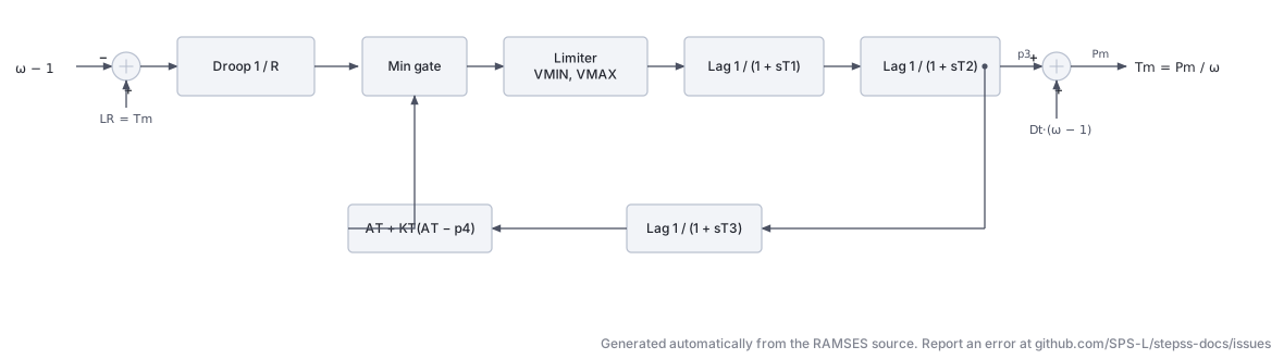
Section titled “Scientific Description”The GAST model represents a gas turbine unit, following the IEEE Committee Report (1973) and the convention common to industry tools. It captures the speed governor, compressor discharge lag, and fuel/combustion dynamics.
Speed governor with droop and load reference:
where (load reference, initialised from mechanical torque) and is the droop.
The speed error drives a value position through a limiter and a first-order lag :
The compressor discharge is modelled by lag :
The mechanical power (including speed-dependent damping ) is:
The exhaust temperature is tracked by a lag :
A temperature limit is applied via:
A minimum gate blocks the valve position: .
The torque-power conversion:
Parameters
Section titled “Parameters”| Parameter | Description |
|---|---|
R | Permanent speed droop (pu/pu) |
T1 | Governor/valve time constant (s) |
T2 | Compressor discharge time constant (s) |
T3 | Radiation shield / exhaust temperature lag (s) |
AT | Ambient temperature load limit (pu) |
KT | Temperature control loop gain |
VMAX | Maximum valve position (pu) |
VMIN | Minimum valve position (pu) |
DTURB | Turbine damping factor (pu torque / pu speed) |
Internal parameter: LR = Tm (load reference, set at initialisation)
Usage Example
Section titled “Usage Example”SYNC_MACH g1 g1 1. 1. 0. 0. 400. 360. 6. 0. 2.05 XT 0.15 2.2 0.3 0.2 2. 0.4 0.2 0.1 6.0257 0. 7.00 0.05 1.5 0.05 EXC GENERIC1 3.0618 -0.1 1. 0. 100. -1. -20.0 10. 120. 5. 12.5 0.1 0. 5. 1 75. 15. 0.22 0.012 0.22 0.012 -0.1 0.1 TOR GAST 0.05 ! R: permanent droop (pu/pu) 0.40 ! T1: governor/valve time constant (s) 0.10 ! T2: compressor discharge time constant (s) 3.00 ! T3: exhaust temperature lag (s) 1.00 ! AT: ambient temperature load limit (pu) 2.50 ! KT: temperature control loop gain 1.05 ! VMAX: maximum valve position (pu) 0.0 ! VMIN: minimum valve position (pu) 0.0 ; ! DTURB: turbine damping factor- Based on the IEEE Committee Report on “Dynamic Models for Steam and Hydro Turbines in Power System Studies” (1973), later adapted for gas turbines.
ATandKTdefine the exhaust-temperature protection characteristic.DTURB = 0disables speed-dependent damping.- Parameters are listed in order:
R T1 T2 T3 AT KT VMAX VMIN DTURB.
TGOV1 (tor_TGOV1D)
Section titled “TGOV1 (tor_TGOV1D)”Scientific Description
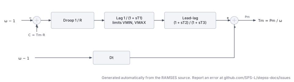
Section titled “Scientific Description”The TGOV1 model represents a simple steam turbine governor, based on the IEEE TGOV1 structure with an added damping term. It is one of the most widely used simple governor models in power-system stability studies.
Speed governor with permanent droop:
The speed error (with droop ) drives a first-order lag with output limits :
Turbine with reheater and damping:
The valve position passes through a lead–lag block representing the steam chest and reheater:
The total mechanical power includes a speed-dependent damping term :
Hence the mechanical torque:
Parameters
Section titled “Parameters”| Parameter | Description |
|---|---|
R | Permanent speed droop (pu/pu) |
T1 | Steam chest / valve actuator time constant (s) |
VMAX | Maximum valve position (pu) |
VMIN | Minimum valve position (pu) |
T2 | Lead time constant, reheater zero (s) |
T3 | Lag time constant, reheater pole (s) |
Dt | Turbine damping coefficient (pu torque / pu speed deviation) |
Internal parameter: C = Tm · R (initialised from load-flow mechanical torque)
Usage Example
Section titled “Usage Example”SYNC_MACH g1 g1 1. 1. 0. 0. 400. 360. 6. 0. 2.05 XT 0.15 2.2 0.3 0.2 2. 0.4 0.2 0.1 6.0257 0. 7.00 0.05 1.5 0.05 EXC GENERIC1 3.0618 -0.1 1. 0. 100. -1. -20.0 10. 120. 5. 12.5 0.1 0. 5. 1 75. 15. 0.22 0.012 0.22 0.012 -0.1 0.1 TOR TGOV1 0.05 ! R: permanent droop (pu/pu) 0.50 ! T1: steam chest/valve actuator time constant (s) 1.05 ! VMAX: maximum valve position (pu) 0.0 ! VMIN: minimum valve position (pu) 2.10 ! T2: lead time constant, reheater zero (s) 7.00 ! T3: lag time constant, reheater pole (s) 0.0 ; ! Dt: turbine damping coefficient- This is essentially the IEEE TGOV1 model with an additional damping term .
- Setting gives a pure first-order turbine .
- adds a stabilising speed-dependent power correction (useful for islanded operation).
- Parameters are listed in order:
R T1 VMAX VMIN T2 T3 Dt.
HYGOV (tor_hygov)
Section titled “HYGOV (tor_hygov)”Scientific Description
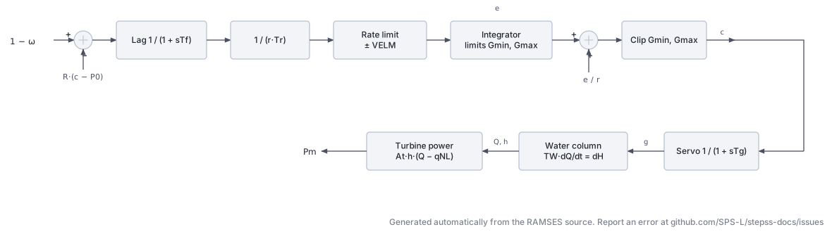
Section titled “Scientific Description”The HYGOV model represents a hydraulic turbine and governor following a simplified penstock/water-column formulation, consistent with the IEEE representation for hydro governors (IEEE Std 1110).
Governor with droop and PI controller:
The speed error (with permanent droop and transient droop ) enters a lag to produce the error signal :
The rate of change of gate demand is computed via the transient droop:
This is rate-limited to , then integrated with gate limits :
The PI controller output (desired gate) is:
The actual gate position follows through the servo:
Penstock / water column:
The head deviation is determined by the non-linear water flow equation and water-starting time :
Turbine mechanical torque:
Parameters
Section titled “Parameters”| Parameter | Description |
|---|---|
R | Permanent droop (pu/pu) |
r | Transient droop (pu/pu) |
Tr | Transient droop reset time (s) |
Tf | Filter time constant for speed error (s) |
Tg | Gate servo time constant (s) |
VELM | Gate velocity limit (pu/s) |
Gmax | Maximum gate opening (pu) |
Gmin | Minimum gate opening (pu) |
Tw | Water starting time (s) |
At | Turbine gain (pu power / pu flow) |
Dturb | Turbine damping factor |
Qnl | No-load water flow (pu) |
Internal parameter: Po = (P / At) + Qnl (initial gate setpoint from load-flow)
Usage Example
Section titled “Usage Example”SYNC_MACH g1 g1 1. 1. 0. 0. 800. 760. 3. 0. 0.95 XT 0.15 1.1 0.25 0.2 0.7 * 0.2 0.1 6.0257 0. 5.00 0.05 * 0.1 EXC GENERIC1 1.8991 -0.1 0. 1. 100. -1. -11 10. 70. 10. 20. 0.1 0. 4. 1 75. 15. 0.2 0.01 0.2 0.01 -0.1 0.1 TOR HYGOV 0.05 ! R: permanent droop (pu/pu) 0.30 ! r: transient droop (pu/pu) 5.00 ! Tr: transient droop reset time (s) 0.05 ! Tf: filter time constant for speed error (s) 0.20 ! Tg: gate servo time constant (s) 0.20 ! VELM: gate velocity limit (pu/s) 1.00 ! Gmax: maximum gate opening (pu) 0.0 ! Gmin: minimum gate opening (pu) 1.50 ! Tw: water starting time (s) 1.10 ! At: turbine gain (pu power / pu flow) 0.50 ! Dturb: turbine damping factor 0.05 ; ! Qnl: no-load water flow (pu)Tw(water starting time) is the dominant parameter controlling frequency response; typical values are 0.5–2 s.r > Ris required for stable regulation; set –5 .Tris the reset time for transient droop; values of 5–30 s are typical.- Non-linear head-flow equation makes this model suitable for large transients.
- Parameters are listed in order:
R r Tr Tf Tg VELM Gmax Gmin Tw At Dturb Qnl.