

Power Flow
Helios is the STEPSS AC power-flow engine. It solves the Newton-Raphson power flow in polar coordinates with reactive limit enforcement, transformer tap adjustment and SVC modelling, and it produces the operating point that initialises a RAMSES dynamic simulation.
Helios is reached two ways, both reading the same data files:
- Run power flow on the Power Flow Simulation tab of STEPSS GUI, which carries the engine rather than asking you to download it;
stepss.helios.HeliosSessionfrom Python, see Power Flow with Helios.
A C API shared library (libhelios_api) exists underneath both, for embedding the engine in another tool.
The power flow uses the following network records documented in Network Modeling: BUS, LINE, SWITCH, TRANSFO, TRFO, NRTP.
The additional records specific to power flow computations are documented below.
Watch it
Section titled “Watch it”Episode 3 of the video series, Helios in Depth, covers this page.
Load and Shunt Data
Section titled “Load and Shunt Data”Load and shunt data are specified in an extended version of the BUS record:
BUS NAME VNOM PLOAD QLOAD BSHUNT QSHUNT ;| Field | Description | Unit |
|---|---|---|
NAME | Bus name (max 8 characters) | |
VNOM | Nominal voltage | kV |
PLOAD | Total active power load (positive = consumed) | MW |
QLOAD | Total reactive power load (positive = consumed) | Mvar |
BSHUNT | Nominal reactive power of constant-susceptance shunt: the reactive power produced under the nominal voltage of the bus (positive = capacitor, negative = reactor) | Mvar |
QSHUNT | Reactive power of constant-power shunt (positive = capacitor) | Mvar |
If no load is connected to the bus, set PLOAD and QLOAD to zero. If no shunt is connected, set BSHUNT and QSHUNT to zero. QSHUNT is optional: a five-field BUS record is accepted and QSHUNT defaults to zero.
The total reactive power produced by both shunt components:
Generator Data
Section titled “Generator Data”GENER NAME BUS P Q VIMP SNOM QMIN QMAX BR ;| Field | Description | Unit |
|---|---|---|
NAME | Generator name (max 20 characters) | |
BUS | Connection bus name | |
P | Active power produced | MW |
Q | Reactive power produced (ignored if VIMP ≠ 0) | Mvar |
VIMP | Imposed voltage (0 = PQ bus, nonzero = PV bus) | pu |
SNOM | Nominal apparent power | MVA |
QMIN | Lower reactive power limit | Mvar |
QMAX | Upper reactive power limit | Mvar |
BR | Breaker status (0 = open) |
For PV buses, if the upper reactive power limit QMAX is exceeded, the bus switches to PQ type with QMAX enforced, and Newton iterations continue. If subsequently the bus voltage rises above VIMP, the bus switches back to PV type. Similarly, if QMIN is exceeded, the bus switches to PQ type with QMIN enforced; it switches back to PV if the voltage subsequently drops below VIMP.
QMIN and QMAX are used only if VIMP is nonzero (PV bus).
An extended variant with active power limits and a participation factor exists:
GENER NAME BUS P Q VIMP SNOM QMIN QMAX PMIN PMAX PART BR ;| Field | Description | Unit |
|---|---|---|
PMIN | Minimum active power the generator can produce | MW |
PMAX | Maximum active power the generator can produce | MW |
PART | Participation factor used when redistributing an active power imbalance |
PMIN/PMAX are not enforced during Newton iterations. They are used to clamp the specified P before the computation (the slack generator is exempted by default; see $PLIM below), and together with PART when generation is redispatched after system modifications or contingencies.
Both variants also accept an additional bus-name field between BUS and P (making 10 or 13 fields in total); that field is accepted and ignored.
Only one generator is allowed per bus.
All generators are memorized, even those which are disconnected. A disconnected generator has zero power output but can be put into service during dynamic simulation.
Slack Bus
Section titled “Slack Bus”A slack bus is mandatory for power flow computations: not all buses can be of PV or PQ type, since this would require knowing the active power losses in the network before performing the calculation.
A PV-type generator must be connected to the slack bus. Its voltage magnitude (from the GENER record) is imposed, and the voltage phase angle is set to zero.
SLACK NAME ;| Field | Description |
|---|---|
NAME | Bus name (max 8 characters) |
There must be exactly one SLACK record in the data.
Only one connected network (island) is solved. If the graph is disconnected, only the sub-network containing the slack bus is treated; equipment on the discarded buses is disabled and the lost active power is reported so that it can be redispatched.
Static Var Compensators (SVC)
Section titled “Static Var Compensators (SVC)”Although reference is made to an SVC, the model can be used in general for any component controlling voltage with a droop. The SVC is assumed lossless: the active current injected at the controlled bus is zero.
The SVC is modeled with a controllable susceptance at a controlled bus , regulating the voltage at a monitored bus :
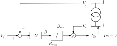
Data Format
Section titled “Data Format”SVC NAME CON_BUS MON_BUS V0 Q0 SNOM BMAX BMIN G BR ;| Field | Description | Unit |
|---|---|---|
NAME | SVC name (max 20 characters) | |
CON_BUS | Controlled bus where the susceptance is varied (max 8 characters) | |
MON_BUS | Monitored bus whose voltage is regulated (max 8 characters) | |
V0 | Voltage setpoint (0 = constant power mode with , , no limits tested) | pu |
Q0 | Reactive power setpoint (ignored if V0 ≠ 0) | Mvar |
SNOM | Nominal reactive power | Mvar |
BMAX | Maximal nominal reactive power: reactive power produced under pu when | Mvar |
BMIN | Minimal nominal reactive power: reactive power produced under pu when | Mvar |
G | Gain, in pu on the (, SNOM) base, where is the nominal voltage at the controlled bus | pu |
BR | Breaker status (0 = open, other = closed) |
It is common for BMAX to be positive and BMIN negative, but other combinations are allowed.
For SVCs with nonzero V0, the voltage control equation is solved initially. If the susceptance upper limit BMAX is exceeded, the limit is enforced and Newton iterations continue. The SVC reverts to voltage control when . Similarly, if BMIN is exceeded, the lower limit is enforced; the SVC reverts when .
Only one SVC is allowed per bus. It is not allowed to connect both a generator and an SVC to the same bus.
All SVCs are memorized, even those which are disconnected. A disconnected SVC can be put into service during dynamic simulation.
Transformer Ratio Adjustment for Voltage Control
Section titled “Transformer Ratio Adjustment for Voltage Control”The ratio of a designated transformer can be adjusted to bring a controlled voltage inside a deadband , where is the desired voltage and is the tolerance.
The ratio is changed in discrete steps between a minimum and maximum value. During computation, the ratio is changed by one step at a time, after which Newton iterations run until convergence. The process repeats until the controlled voltage falls in the deadband. When multiple transformers are adjusted, some may reach their deadbands before others.
Via TRFO Record
Section titled “Via TRFO Record”The controlled bus is CONBUS in the TRFO record. This must be one of the two ending buses of the transformer. An empty or blank string enclosed within quotes indicates that the transformer ratio is not to be adjusted; in this case, dummy values must still be provided for the remaining fields.
The ratio corresponding to tap position ():
The initial ratio from the N field of the TRFO record is adjusted to the nearest tap position before starting the power flow computation.
Relevant fields in the TRFO record:
| Field | Description | Unit |
|---|---|---|
NFIRST | Ratio at first tap position (lower bound) | % |
NLAST | Ratio at last tap position (upper bound) | % |
NBPOS | Total number of tap positions (including first and last) | |
TOLV | Voltage tolerance | pu |
VDES | Desired voltage | pu |
Via LTC-V Record
Section titled “Via LTC-V Record”The second way to specify ratio adjustment is through a separate LTC-V record. This is more natural in association with a TRANSFO record.
LTC-V NAME CON_BUS NFIRST NLAST NBPOS TOLV VDES ;| Field | Description | Unit |
|---|---|---|
NAME | Name of the controlled transformer (max 20 characters) | |
CON_BUS | Controlled bus (max 8 characters) | |
NFIRST | Ratio at first tap position (lower bound) | % |
NLAST | Ratio at last tap position (upper bound) | % |
NBPOS | Total number of tap positions (including first and last) | |
TOLV | Voltage tolerance | pu |
VDES | Desired voltage | pu |
A transformer can be controlled by a single tap changer only. The LTC-V record can also be associated with a TRFO record, provided that no adjustment is specified in the TRFO record itself.
Only this seven-field linear-ratio form is supported; there is no per-tap reactance variant.
Phase-Shifting Transformer Adjustment (PSHIFT-P)
Section titled “Phase-Shifting Transformer Adjustment (PSHIFT-P)”The phase angle of a transformer can be adjusted to bring the active power flow in a monitored branch inside a deadband . The adjustment mechanism is similar to the in-phase ratio adjustment described above.
PSHIFT-P CONTRFO MONBRANCH PHAFIRST PHALAST NBPOS SIGN PDES TOLP ;| Field | Description | Unit |
|---|---|---|
CONTRFO | Name of the transformer whose phase angle is adjusted (max 20 characters, defined in a TRFO or TRANSFO record). If the transformer does not exist, the record is ignored with a warning | |
MONBRANCH | Name of the branch where active power is monitored (max 20 characters, defined in a LINE, TRFO, or TRANSFO record). is the active power leaving the first bus of the branch record | |
PHAFIRST | Phase angle at first tap position (lower bound) | degrees |
PHALAST | Phase angle at last tap position (upper bound) | degrees |
NBPOS | Number of tap positions | |
SIGN | Direction indicator: 1 means must increase to increase power flow; -1 means decrease. Any other value causes the program to stop | |
PDES | Desired active power flow | MW |
TOLP | Tolerance | MW |
The phase angle at tap position () is:
The initial phase angle from the PHI field of the TRANSFO record is adjusted to the nearest tap position before starting the power flow computation.
A sensitivity analysis determines whether the phase angle should be increased or decreased. If this analysis indicates a direction opposite to SIGN, a warning is issued and SIGN is ignored. On output, SIGN is set to the value from the sensitivity analysis.
Only one PSHIFT-P record per transformer is allowed. The PSHIFT-P record is intended for use with a TRANSFO record, but can also be used with a TRFO record (in which case the angle is initialized to zero).
A transformer cannot be controlled by both an LTC-V and a PSHIFT-P record.
A detailed form with per-tap data (10 + 4k fields) is also accepted.
Zone and Cut Aggregation
Section titled “Zone and Cut Aggregation”Two optional records group equipment for reporting. They do not affect the solution.
BUSPART ZONE_NAME BUS_NAME PARTP PARTQ ;| Field | Description |
|---|---|
ZONE_NAME | Zone name; the zone is created on first use |
BUS_NAME | Bus to include in the zone (max 8 characters) |
PARTP | Active power participation weight of this bus in the zone |
PARTQ | Reactive power participation weight of this bus in the zone |
Zones drive the zone-power display and the zone-wide load and generation changes of the modify menu. Buses with unrecognised names are skipped.
BRAPART CUT_NAME BRANCH_NAME BUS_NAME SIGN ;| Field | Description |
|---|---|
CUT_NAME | Cut name; the cut is created on first use |
BRANCH_NAME | Branch to include in the cut (max 20 characters) |
BUS_NAME | One endpoint of the branch, fixing the direction of the flow that is summed |
SIGN | +1 or -1, applied to that branch’s contribution |
The cut power is the signed sum of the member branch flows, reported per branch and as a total.
Bus Voltages: Initial Values and Results (LFRESV)
Section titled “Bus Voltages: Initial Values and Results (LFRESV)”On output, the power flow produces a file with the computed bus voltage magnitudes and phase angles. These are stored in LFRESV records. The syntax is:
LFRESV BUS MODV PHASV ;| Field | Description | Unit |
|---|---|---|
BUS | Bus name (max 8 characters) | |
MODV | Voltage magnitude | pu |
PHASV | Voltage phase angle, referenced to slack bus | radians |
Computation Control Parameters
Section titled “Computation Control Parameters”The power flow uses Newton-Raphson iterations to solve the power flow equations. Convergence is achieved when both the active and reactive power mismatches fall below specified thresholds, all transformer ratio and phase-shift controls are satisfied, and all generators and SVCs are within their reactive limits.
Three convergence indices are used:
- : largest absolute mismatch of the active power equations
- : largest absolute mismatch of the reactive power equations
- : largest apparent power mismatch, used to trigger limit checks (via
$MISQLIM), factorization reuse (via$MISBLOC), and transformer adjustments (via$MISADJ)
The following records control the computation. Each record starts with $ and has a single numeric field; a known $ record with any other field count is a hard error, and an unknown $ key is ignored.
| Parameter | Default | Unit | Description |
|---|---|---|---|
$SBASE | 100 | MVA | System base power (on which pu values are expressed) |
$TOLAC | 0.1 | MW | Convergence tolerance on active power mismatch () |
$TOLREAC | 0.1 | Mvar | Convergence tolerance on reactive power mismatch () |
$NBITMA | 20 | Maximum number of Newton iterations | |
$MISQLIM | 20 | MVA | Apparent power mismatch threshold below which generator/SVC reactive limits are checked and enforced (set to 0 to skip) |
$MISBLOC | 10 | MVA | Apparent power mismatch threshold below which the Jacobian factorization reuses the previous pivot ordering. Jacobian values are recomputed at every iteration regardless |
$MISADJ | 10 | MVA | Apparent power mismatch threshold below which transformer ratios and phase shifts are adjusted (set to 0 to skip) |
$DIVDET | 0 | Set to 1 to activate divergence detection; 0 to skip | |
$PLIM | 1 | 1 = the slack generator’s PMIN/PMAX are bypassed during initial P clamping; 0 = the slack is clamped like any other generator |
$PLIM only affects 12/13-field GENER records, the only ones that carry real active power limits.
Exit Status
Section titled “Exit Status”In non-interactive use (-t command file mode and pipe mode), Helios reports the outcome of the run through its process exit status:
| Exit | Meaning |
|---|---|
0 | Converged, the results are usable |
1 | Input or usage error: bad command file, unreadable data file, parse failure, unknown command |
2 | The solve ran but did not converge: maximum iterations, divergence, or a singular Jacobian. Results may still have been written, but they are not a valid power-flow solution |
Only 0 means the results can be trusted. Where a command file modifies the system and re-solves, the status reflects the final solve. The interactive TUI always exits 0.
Each non-interactive run also writes one machine-readable line to stderr:
helios: status: CONVERGED (2 iterations)helios: status: NOT_CONVERGED (max iterations)helios: status: NOT_CONVERGED (diverged)helios: status: NOT_CONVERGED (singular)helios: status: NOT_RUNNOT_RUN means no solve was requested (for example $NBITMA 0), which exits 0. Scripts should use the exit status and this line rather than parsing stdout.
These values are shared with the Helios C API, where HELIOS_OK is 0 and HELIOS_NOT_CONVERGED is 2 (1 is reserved and never returned by the API). HELIOS_NOT_CONVERGED is 2 from Helios 1.4.1 onward; in 1.3.0 and earlier it was 1. The stepss.helios.HeliosSession wrapper exposes convergence as the boolean pf.converged and the pf.solver_status enum, neither of which is affected by the numbering.
Record Sharing Between Power Flow and RAMSES
Section titled “Record Sharing Between Power Flow and RAMSES”The following table summarises which records are used by the power flow and by RAMSES respectively.
| Record | Power flow | RAMSES |
|---|---|---|
| BUS | All 6 fields (QSHUNT optional) | First 2 fields (NAME, VNOM) |
| LINE | All fields | All fields |
| SWITCH | All fields | All fields |
| NRTP | All fields | All fields |
| TRANSFO | All fields | All fields |
| TRFO | All fields | Fields 1 to 9 and 15 only |
| SHUNT | Ignored | All fields |
| GENER | All fields | Ignored |
| SVC | All fields | Ignored |
| SLACK | Used | Used |
| LFRESV | Input: initial values; Output: solution | Input: initial values for RAMSES |
| LTC-V | Used | Ignored |
| PSHIFT-P | Used | Ignored |
| BUSPART, BRAPART | Used for reporting | Ignored |
Annotated One-line Diagram
Section titled “Annotated One-line Diagram”Helios can render a solved case onto an SVG drawing of the network instead of, or alongside, reading the same numbers off a table.
A template is an SVG file with placeholder codes typed into its text elements as plain text. Any general-purpose SVG editor works: Helios finds a placeholder by its text content when it renders, not by any tool-specific metadata. A placeholder is a code letter directly followed by its argument, with no space, so %A (bus voltage magnitude) applied to bus E is written %AE. A branch code takes the branch name and the bus end separated by a comma: %D (P flow) on branch D-E at its E end is %DD-E,E.
| Code | Argument | Value |
|---|---|---|
%A | bus | voltage magnitude (pu) |
%B | bus | voltage (kV) |
%C | bus | angle (degrees) |
%D | branch, bus | P flow at that bus end (MW) |
%E | branch, bus | Q flow at that bus end (Mvar) |
%F | branch | loading fraction |
%G | generator | P (MW) |
%H | bus | shunt Q (Mvar) |
%J | transformer | tap position |
%K | generator | Q (Mvar) |
%L | SVC | Q (Mvar) |
%R | bus | load P (MW) |
%S | bus | load Q (Mvar) |
%T | branch | breaker status, blank or X |
%U | generator | breaker status, blank or X |
Every Run power flow in the GUI runs this substitution; from Python, pf.write_diagram('template.svg', 'diagram.svg') does the same, see Power Flow with Helios.
In STEPSS GUI
Section titled “In STEPSS GUI”The template is an optional third slot on the System Data tab, alongside the data and disturbance files (the disturbance file on that tab is optional too, which is what makes a power-flow-only case a normal thing to load). Its button opens the named file in the platform’s default SVG viewer or editor, for authoring or checking placeholders.
Every Run Power Flow renders the template with the solved values and opens the result in a window of its own. Each run opens a new window, offset from the last one, so two runs can be compared side by side. The window offers Fit, Zoom in and Zoom out as buttons; the wheel zooms anchored at the pointer; dragging pans; double-click returns to Fit; and Save as PNG and Save as SVG save the result. Save as PNG saves the whole diagram, not only what is currently in view. A run that does not converge still opens a window, with a banner carrying the same status the main window’s status bar shows.
Worked example: SPS-L/stepss-6-bus-MG, bundled in STEPSS GUI under File > Open Examples, ships 6bus.svg, a template carrying these placeholder codes; Run Power Flow fills it in with the solved voltages, angles and flows.
Next Steps
Section titled “Next Steps”- Reference Frames & Initialization, Understand how RAMSES initializes from the power flow solution
- Dynamic Data Records, Define synchronous machines, injectors, and controllers