

Compensation and Measurement
Two injector models that are neither loads nor generators: a static var compensator and a phasor measurement unit.
The INJEC record these models are entered with, and the rules on model names, are on the Injector Models page.
SVC_GENERIC1 (inj_svc_generic1): Generic Static Var Compensator
Section titled “SVC_GENERIC1 (inj_svc_generic1): Generic Static Var Compensator”The data-file model name is SVC_GENERIC1. It takes no prefix.
Description
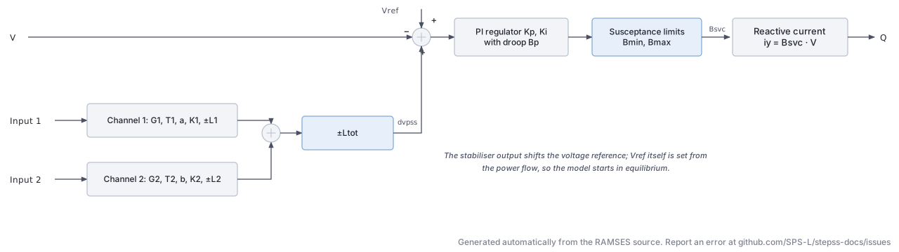
Section titled “Description”A dynamic SVC injecting a purely reactive current at its bus. A PI voltage
regulator with droop drives a susceptance between Bmin and Bmax,
and two lead-lag stabiliser channels can add a supplementary signal to the
voltage reference. This is the dynamic counterpart of the static
SVC record used by the
power flow: the static record fixes the operating point, this model governs how
the device behaves during the simulation.
The voltage reference is initialised from the power flow solution, so that the model starts in equilibrium:
where is the droop and the initial susceptance implied by the reactive current at the bus.
Parameters
Section titled “Parameters”The record carries 17 data parameters, in order:
| # | Name | Description |
|---|---|---|
| 1 | G1 | Gain of the first stabiliser channel |
| 2 | T1 | Time constant of the first stabiliser channel (s) |
| 3 | a | Lead-lag coefficient of the first channel |
| 4 | K1 | Output gain of the first channel |
| 5 | L1 | Output limit of the first channel (pu) |
| 6 | G2 | Gain of the second stabiliser channel |
| 7 | T2 | Time constant of the second stabiliser channel (s) |
| 8 | b | Lead-lag coefficient of the second channel |
| 9 | K2 | Output gain of the second channel |
| 10 | L2 | Output limit of the second channel (pu) |
| 11 | Ltot | Limit on the summed stabiliser output (pu) |
| 12 | Kp | Proportional gain of the voltage regulator |
| 13 | Ki | Integral gain of the voltage regulator |
| 14 | Bp | Droop, in pu on the SVC base |
| 15 | Bmax | Maximum susceptance (Mvar at 1 pu voltage) |
| 16 | Bmin | Minimum susceptance (Mvar at 1 pu voltage) |
| 17 | Bnom | Susceptance base used for the per-unit conversion (Mvar) |
One additional parameter is computed at initialisation:
| # | Name | Description |
|---|---|---|
| 18 | Vref | Voltage reference, set from the power flow solution |
Observables
Section titled “Observables”Q, dvpss, Bsvc, Vref, Vb
PMU (inj_PMU): Phasor Measurement Unit
Section titled “PMU (inj_PMU): Phasor Measurement Unit”The data-file model name is PMU (or inj_PMU).
Description
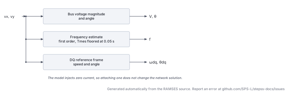
Section titled “Description”A measurement-only injector: it injects zero current at its bus and exists
purely to expose bus quantities as observables. It reports a filtered local
frequency estimate computed the same way as the f_inj block, together with the
bus voltage magnitude and angle and the speed and angle of the moving DQ
reference frame. Attach one to any bus whose frequency you want to record
without perturbing the solution.
The frequency estimate is a first-order filter on the bus voltage phasor. The measurement time constant is clamped to a floor of 0.05 s, so values below that have no effect.
Parameters
Section titled “Parameters”| # | Name | Description | Unit |
|---|---|---|---|
| 1 | Tf | Frequency measurement time constant, recommended 0.05 to 0.10; values below 0.05 are clamped | s |
Three additional parameters are set at initialisation: wnom (nominal angular
frequency), vm0 and va0 (the initial bus voltage magnitude and angle).
Observables
Section titled “Observables”| Name | Description | Unit |
|---|---|---|
f | Estimated bus frequency | pu of |
vm | Bus voltage magnitude | pu |
va | Bus voltage phase angle in the moving DQ frame, wrapping at | rad |
thref | Accumulated angle of the DQ reference frame with respect to the nominally rotating frame, zero at | rad |
dwref | Speed deviation of the DQ reference frame from nominal | rad/s |
Usage Example
Section titled “Usage Example”Show the data record
INJEC PMU PMU_1041 1041 # FP FQ P Q: share of the power-flow injection (FP, FQ) or initial power (P in MW, Q in Mvar) 0. 0. 0. 0. # Tf: Frequency measurement time constant, recommended 0.05 to 0.10; values below 0.05 are clamped (s) 0.05;All four participation and power fields are zero: the model neither consumes nor produces power.