

Induction Machines
Injector models for induction machines, used as motors or generators.
The INJEC record these models are entered with, and the rules on model names, are on the Injector Models page.
INDMACH1 (inj_indmach1): Single-Cage Induction Machine
Section titled “INDMACH1 (inj_indmach1): Single-Cage Induction Machine”Description
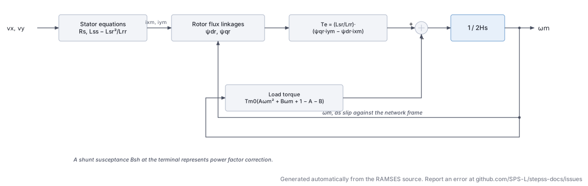
Section titled “Description”A single-cage (single-rotor-circuit) induction machine model for motor loads. The machine is represented on its own MVA base (or inferred from load factor LF) with a shunt capacitor to represent power factor correction. The mechanical torque is a quadratic function of rotor speed. At initialization, the model solves nonlinear algebraic equations to find the operating-point slip and flux linkages.
Scientific Description
Section titled “Scientific Description”The machine uses the standard - reference-frame formulation with and . The rotor flux-linkage equations are:
where and is the rotor mechanical speed. The equations for the stator (with shunt susceptance ) are:
The rotor speed dynamics follow the swing equation:
where the electromagnetic torque is:
and the mechanical torque is the quadratic load curve:
Parameters
Section titled “Parameters”| # | Name | Description | Unit |
|---|---|---|---|
| 1 | SNOM | Machine nominal apparent power (0 = infer from LF) | MVA |
| 2 | RS | Stator resistance | pu |
| 3 | Lls | Stator leakage inductance | pu |
| 4 | LSR | Magnetizing inductance | pu |
| 5 | RR | Rotor resistance | pu |
| 6 | Llr | Rotor leakage inductance | pu |
| 7 | H | Machine inertia constant | s |
| 8 | A | Quadratic torque-speed coefficient | |
| 9 | B | Linear torque-speed coefficient | |
| 10 | LF | Load factor (for SNOM inference) |
State Variables
Section titled “State Variables”| Variable | Description |
|---|---|
iy | -component of stator current |
ix | -component of stator current |
psidr | -axis rotor flux linkage |
psiqr | -axis rotor flux linkage |
omegam | Rotor mechanical speed |
Observables: P, Qmot+comp, Qmot, omega, Tm
Usage Example
Section titled “Usage Example”Show the data record
INJEC INDMACH1 MTR1 BUS_MV # FP FQ P Q: share of the power-flow injection (FP, FQ) or initial power (P in MW, Q in Mvar) 1. 1. 0. 0. # SNOM: Machine nominal apparent power, 0 = infer from LF (MVA) 10.0 # RS: Stator resistance (pu (machine base)) 0.01 # Lls: Stator leakage inductance (pu (machine base)) 0.10 # LSR: Magnetizing inductance (pu (machine base)) 2.50 # RR: Rotor resistance (pu (machine base)) 0.015 # Llr: Rotor leakage inductance (pu (machine base)) 0.10 # H: Inertia constant (s) 1.5 # A: Quadratic coefficient of load torque vs speed 0.8 # B: Linear coefficient of load torque vs speed 0.1 # LF: Load factor, initial P over SNOM, used only when SNOM = 0 0.0;INDMACH2 (inj_indmach2): Double-Cage Induction Machine
Section titled “INDMACH2 (inj_indmach2): Double-Cage Induction Machine”Description
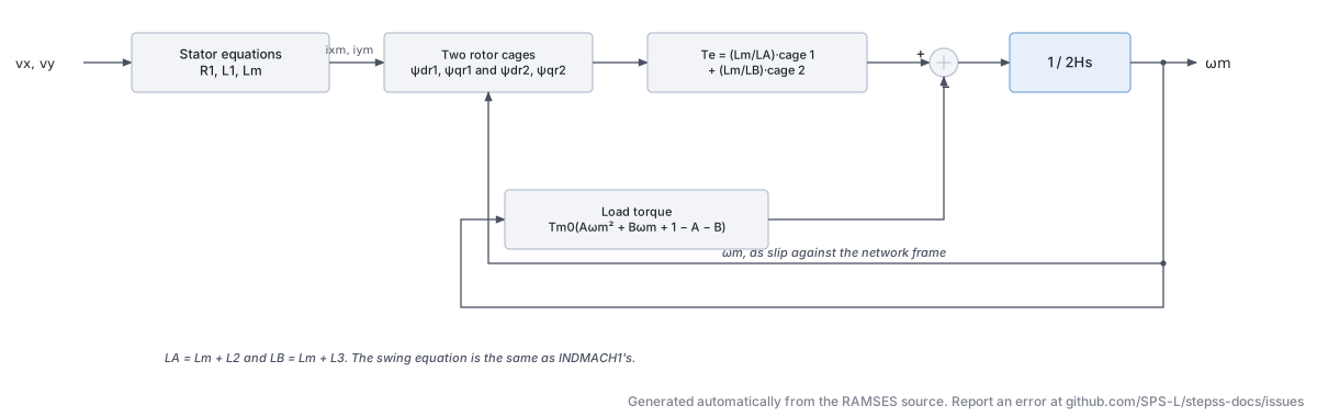
Section titled “Description”A double-cage (double-rotor-circuit) induction machine model following the Eurostag formulation. Two parallel rotor cages allow more accurate representation of the machine’s impedance-vs-frequency characteristic, which is especially important for the starting transient. The model structure mirrors inj_indmach1 but includes a second set of rotor flux states.
Scientific Description
Section titled “Scientific Description”The machine has parameters: stator resistance , stator leakage , magnetizing inductance , cage-1 resistance and leakage , cage-2 resistance and leakage . The state vector is with flux-linkage equations for each cage:
where and . The total electromagnetic torque combines contributions from both cages:
The swing equation is identical to inj_indmach1.
Parameters
Section titled “Parameters”| # | Name | Description | Unit |
|---|---|---|---|
| 1 | SNOM | Machine MVA rating (0 = infer from LF) | MVA |
| 2 | R1 | Stator resistance | pu |
| 3 | L1 | Stator leakage inductance | pu |
| 4 | Lm | Magnetizing inductance | pu |
| 5 | R2 | First cage resistance | pu |
| 6 | L2 | First cage leakage inductance | pu |
| 7 | R3 | Second cage resistance | pu |
| 8 | L3 | Second cage leakage inductance | pu |
| 9 | H | Inertia constant | s |
| 10 | A | Quadratic torque-speed coefficient | |
| 11 | B | Linear torque-speed coefficient | |
| 12 | LF | Load factor (for SNOM inference) |
State Variables
Section titled “State Variables”| Variable | Description |
|---|---|
iy | -component of stator current |
ix | -component of stator current |
psidr1 | -axis flux of first rotor cage |
psiqr1 | -axis flux of first rotor cage |
psidr2 | -axis flux of second rotor cage |
psiqr2 | -axis flux of second rotor cage |
omegam | Rotor mechanical speed |
Observables: P, Qmot+comp, Qmot, omega
Usage Example
Section titled “Usage Example”Show the data record
INJEC INDMACH2 MTR2 BUS_MV # FP FQ P Q: share of the power-flow injection (FP, FQ) or initial power (P in MW, Q in Mvar) 1. 1. 0. 0. # SNOM: Machine nominal apparent power, 0 = infer from LF (MVA) 10.0 # R1: Stator resistance (pu (machine base)) 0.01 # L1: Stator leakage inductance (pu (machine base)) 0.08 # Lm: Magnetizing inductance (pu (machine base)) 2.00 # R2: First cage resistance (pu (machine base)) 0.02 # L2: First cage leakage inductance (pu (machine base)) 0.06 # R3: Second cage resistance (pu (machine base)) 0.04 # L3: Second cage leakage inductance (pu (machine base)) 0.10 # H: Inertia constant (s) 1.5 # A: Quadratic coefficient of load torque vs speed 0.8 # B: Linear coefficient of load torque vs speed 0.1 # LF: Load factor, initial P over SNOM, used only when SNOM = 0 0.0;INDM1 (inj_INDM1): Alternative Induction Machine
Section titled “INDM1 (inj_INDM1): Alternative Induction Machine”The data-file model name is INDM1 (or inj_INDM1).
Description
Section titled “Description”An alternative single-cage induction machine model that uses the INI_indmach1 helper function for initialization. It is equivalent in physics to inj_indmach1 but implements the equations using RAMSES .txt-style model syntax with explicit state initialization calls. This can simplify parameterization when the helper function’s output is directly used.
Scientific Description
Section titled “Scientific Description”The model equations match those of inj_indmach1, whose block diagram applies here unchanged. The key distinction is the use of the INI_indmach1 function at parameter-evaluation time to pre-compute , , and the initial flux linkages and rotor speed, rather than solving the initialization system in Fortran. With and , the rotor flux equations are:
The rotor speed integral uses:
with a lower limit of .
Parameters
Section titled “Parameters”| # | Name | Description | Unit |
|---|---|---|---|
| 1 | SNOM | Machine MVA rating | MVA |
| 2 | RS | Stator resistance | pu |
| 3 | Lls | Stator leakage inductance | pu |
| 4 | LSR | Magnetizing inductance | pu |
| 5 | RR | Rotor resistance | pu |
| 6 | Llr | Rotor leakage inductance | pu |
| 7 | H | Inertia constant | s |
| 8 | A | Quadratic torque-speed coefficient | |
| 9 | B | Linear torque-speed coefficient | |
| 10 | LF | Load factor |
Computed internally: BSH (shunt susceptance), TM0 (initial mechanical torque), LSS, LRR.
State Variables
Section titled “State Variables”| Variable | Description |
|---|---|
Psidr | -axis rotor flux linkage |
Psiqr | -axis rotor flux linkage |
omegam | Rotor mechanical speed |
iym, ixm | Stator current components (on machine base) |
dPsidr, dPsiqr, domegam | Time-derivative auxiliary states |
Observables: omegam
Usage Example
Section titled “Usage Example”Show the data record
INJEC INDM1 MTR3 BUS_MV # FP FQ P Q: share of the power-flow injection (FP, FQ) or initial power (P in MW, Q in Mvar) 1. 1. 0. 0. # SNOM: Machine MVA rating (MVA) 10.0 # RS: Stator resistance (pu) 0.01 # Lls: Stator leakage inductance (pu) 0.10 # LSR: Magnetizing inductance (pu) 2.50 # RR: Rotor resistance (pu) 0.015 # Llr: Rotor leakage inductance (pu) 0.10 # H: Inertia constant (s) 1.5 # A: Quadratic torque-speed coefficient 0.8 # B: Linear torque-speed coefficient 0.1 # LF: Load factor 0.0;