

Tap Changers
The DCTL record these models are entered with, and the rules on model names, are on the Discrete Controller Models page.
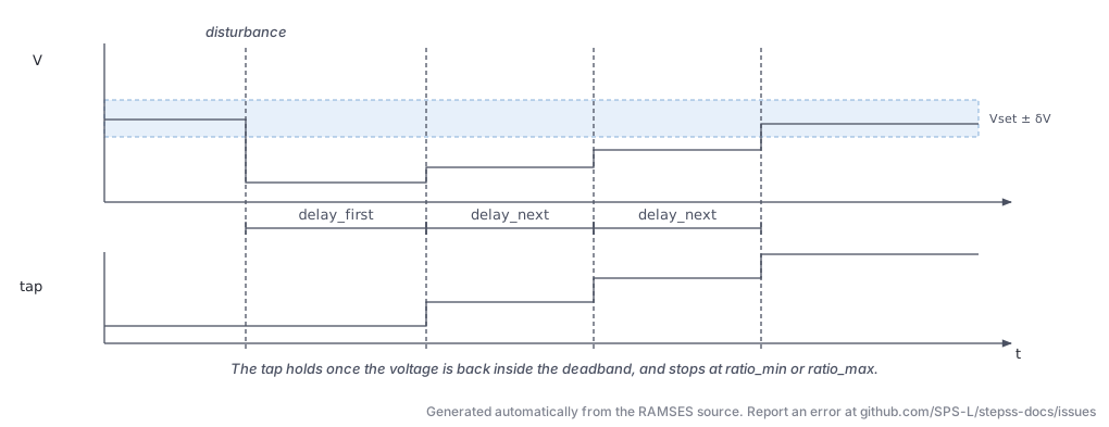
Every controller in this section is a timed automaton rather than a transfer function: it watches a quantity, waits out a delay, then acts. The tap changers share the sequence below, and differ only in how the delay is computed.
LTC (dctl_ltc): Load Tap Changer (Standard)
Section titled “LTC (dctl_ltc): Load Tap Changer (Standard)”Description
Section titled “Description”Controls the ratio of a transformer to regulate voltage at a monitored bus. It monitors the voltage, compares it against a deadband around the setpoint (initialised to the voltage at ), and initiates a tap change after a delay if the voltage remains outside the deadband.
The first tap change uses a longer delay (delay_first); subsequent changes use a shorter delay (delay_next), implementing the standard IEC/IEEE slow-start behaviour.
Logic Description
Section titled “Logic Description”Let be the monitored bus voltage and the setpoint:
Deadband check: No action if (half-deadband).
Direction logic: If direction > 0, increasing the ratio increases the voltage.
Timer logic:
where for the first operation, thereafter, and the tap is clamped to .
State variable w(13):
0: voltage within deadband+1: (tap must increase)−1: (tap must decrease)
Parameters
Section titled “Parameters”| Field | Working variable | Description |
|---|---|---|
branch_name | w(1) | Transformer branch name (must be type trfo) |
bus_name | w(2) | Monitored (controlled) bus name |
direction | w(3) | Sign convention: >0 means increasing ratio raises voltage |
ratio_min | w(4) | Minimum transformer ratio (% of nominal, e.g. 85. for 0.85 pu) |
ratio_max | w(5) | Maximum transformer ratio (% of nominal, e.g. 115. for 1.15 pu) |
nb_positions | w(6) | Number of tap positions (step = (max−min)/(nb−1)) |
half_deadband | w(7) | Voltage half-deadband (pu) |
delay_first | w(8) | Delay before first tap change (s) |
delay_next | w(9) | Delay between subsequent tap changes (s) |
Usage Example
Section titled “Usage Example”Show the data record
DCTL LTC LTC_TR1 # branch: transformer whose ratio is controlled TR1-HV-MV # bus: bus whose voltage is controlled BUS_MV # direction: sign of the ratio change that raises the voltage (only the sign is used, 0 is refused) 1 # ratio_min: minimum ratio (%) 85. # ratio_max: maximum ratio (%) 115. # nb_positions: number of tap positions, at least 2 33 # half_deadband: half of the voltage deadband (pu) 0.01 # delay_first: delay before the first tap change (s) 30.0 # delay_next: delay between subsequent tap changes (s) 10.0;LTC2 (dctl_ltc2): Load Tap Changer (Variant 2)
Section titled “LTC2 (dctl_ltc2): Load Tap Changer (Variant 2)”Description
Section titled “Description”Identical logic to dctl_ltc but the voltage setpoint is an explicit input parameter rather than being taken from the initial operating point. This allows prescribing a setpoint different from the initial bus voltage, which is useful when the initial load-flow voltage differs from the desired operating voltage.
Logic Description
Section titled “Logic Description”Same deadband, direction, and timer logic as dctl_ltc. The voltage setpoint is read directly from the data field Vset instead of being captured at .
Parameters
Section titled “Parameters”| Field | Working variable | Description |
|---|---|---|
branch_name | w(1) | Transformer branch (type trfo) |
bus_name | w(2) | Monitored bus |
direction | w(3) | >0: ratio increase raises voltage |
ratio_min | w(4) | Minimum ratio (% of nominal) |
ratio_max | w(5) | Maximum ratio (% of nominal) |
nb_positions | w(6) | Number of tap positions |
half_deadband | w(7) | Voltage half-deadband (pu) |
Vset | w(8) | Voltage setpoint (pu) |
delay_first | w(9) | First tap change delay (s) |
delay_next | w(10) | Subsequent tap change delay (s) |
Usage Example
Section titled “Usage Example”Show the data record
DCTL LTC2 LTC2_TR1 # branch: transformer whose ratio is controlled TR1-HV-MV # bus: bus whose voltage is controlled BUS_MV # direction: sign of the ratio change that raises the voltage (only the sign is used, 0 is refused) -1 # ratio_min: minimum ratio (%) 88. # ratio_max: maximum ratio (%) 120. # nb_positions: number of tap positions, at least 2 33 # half_deadband: half of the voltage deadband (pu) 0.01 # Vset: voltage setpoint (pu) 1.0 # delay_first: delay before the first tap change (s) 30 # delay_next: delay between subsequent tap changes (s) 8;LTCINV (dctl_ltcinv): Inverse-Time Load Tap Changer
Section titled “LTCINV (dctl_ltcinv): Inverse-Time Load Tap Changer”Description
Section titled “Description”An inverse-time tap changer in which the delay before a tap change is proportional to the integral of the voltage deviation rather than a fixed timer. Large voltage errors trigger faster operation; small but persistent deviations trigger slower operation.
This implements behaviour analogous to inverse-time overcurrent relays, applied to voltage control.
Logic Description
Section titled “Logic Description”The controller integrates the signed voltage deviation over time:
A tap change fires when the integrated error exceeds a threshold derived from the maximum delay and acceleration parameter:
where is the maximum delay and accel is the acceleration factor (smaller value = faster response).
State variable w(13): same coding as dctl_ltc.
Parameters
Section titled “Parameters”| Field | Working variable | Description |
|---|---|---|
branch_name | w(1) | Transformer branch |
bus_name | w(2) | Monitored bus |
direction | w(3) | Sign convention |
ratio_min | w(4) | Minimum ratio (% of nominal) |
ratio_max | w(5) | Maximum ratio (% of nominal) |
nb_positions | w(6) | Number of tap positions |
half_deadband | w(7) | Voltage half-deadband (pu) |
Vset | w(8) | Voltage setpoint (pu) |
delay_max | w(9) | Maximum delay before tap change (s) |
accel | w(10) | Acceleration factor (s), smaller = faster |
Usage Example
Section titled “Usage Example”Show the data record
DCTL LTCINV LTCINV_TR1 # branch: transformer whose ratio is controlled TR1-HV-MV # bus: bus whose voltage is controlled BUS_MV # direction: sign of the ratio change that raises the voltage (only the sign is used, 0 is refused) 1 # ratio_min: minimum ratio (%) 85. # ratio_max: maximum ratio (%) 115. # nb_positions: number of tap positions, at least 2 33 # half_deadband: half of the voltage deadband (pu) 0.01 # Vset: voltage setpoint (pu) 1.025 # delay_max: delay for a voltage error equal to the half deadband (s) 60.0 # accel: time subtracted from the inverse-time delay (s) 0.1;OLTC2 (dctl_oltc2): On-Load Tap Changer Type 2
Section titled “OLTC2 (dctl_oltc2): On-Load Tap Changer Type 2”Description
Section titled “Description”An advanced on-load tap changer with R/X line drop compensation, end-stop flags. It includes separate flags to prevent tap movement when the transformer is at its mechanical end-stop, and applies voltage correction based on the current flowing through the transformer using the compensation resistances R_comp and X_comp.
The Ratio2-factor enables a secondary correction factor for the transformer ratio independent of the main tap position.
Logic Description
Section titled “Logic Description”Compensated voltage seen by the controller:
where are the real and imaginary components of the transformer current. The deadband check and timer logic then operate on .
End-stop flags w(15) and w(16) prevent further tap changes when the ratio is already at its limit and the requested change would move it beyond.
Parameters
Section titled “Parameters”| Field | Working variable | Description |
|---|---|---|
branch_name | w(1) | Transformer branch |
bus_name | w(2) | Controlled bus |
direction | w(3) | Sign convention |
ratio_min | w(4) | Minimum ratio (pu) |
ratio_max | w(5) | Maximum ratio (pu) |
nb_positions | w(6) | Number of tap positions |
half_deadband | w(7) | Voltage half-deadband (pu) |
Vset | w(8) | Voltage setpoint (pu) |
delay_first | w(9) | First tap change delay (s) |
delay_next | w(10) | Subsequent tap change delay (s) |
R_comp | w(17) | Line drop compensation resistance (pu) |
X_comp | w(18) | Line drop compensation reactance (pu) |
ratio2_factor | w(20) | Secondary ratio correction factor (pu) |
14 fields required (includes from-bus, to-bus, circuit ID for PSS/E format).
Usage Example
Section titled “Usage Example”Show the data record
DCTL OLTC2 OLTC_TR2 # branch: transformer whose ratio is controlled TR1-HV-MV # bus: bus whose voltage is controlled BUS_MV # direction: sign of the ratio change that raises the voltage (0 locks the tap) 1 # ratio_min: minimum ratio (%) 88. # ratio_max: maximum ratio (%) 112. # nb_positions: number of tap positions, at least 2 25 # half_deadband: half of the voltage deadband (pu) 0.0075 # Vset: voltage setpoint; the initial voltage must lie within Vset +/- half_deadband (pu) 1.02 # delay_first: delay before the first tap change (s) 45.0 # delay_next: delay between subsequent tap changes (s) 15.0 # R_comp: line-drop compensation resistance (pu) 0.0 # X_comp: line-drop compensation reactance (pu) 0.0 # verbose: 1 = full log messages; any other value gives fewer 1 # ratio2_factor: scales the tap ratio printed in log messages only 1.0;