

IEEE ST and Other Exciters
The static (ST) exciters of IEEE Std 421.5, the IEEET5 and SEXS models, and the ENTSO-E simplified exciter.
The EXC sub-record these models are entered with, and the table of IEEE model variants, are on the Exciter Models page.
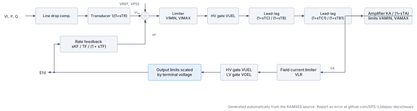
The ST1A is a static (thyristor) excitation system with two cascaded lead-lag networks in the voltage regulator path and an inner field current limiter (KLR/ILR). It corresponds to IEEE Std 421.5-2016 Type ST1A. The output limits are proportional to terminal voltage , and field current derating applies through : .
Mathematical Description
Section titled “Mathematical Description”The voltage regulator with dual lead-lag and instantaneous field current limiting:
Instantaneous field current limiter:
Final output with terminal-voltage-dependent limits:
Derivative feedback:
Signal Flow
Section titled “Signal Flow”- Line drop (
algeq): - Measurement filter (
tf1p): with - AVR summation (
algeq): , including UEL (mode 1), PSS, and VF - Error limiter (
lim): - UEL gate (mode 2) (
max1v1c): HV gate - First lead-lag (
tf1p1z): with - Second lead-lag (
tf1p1z): with - Amplifier (
tf1plim): with , , - Field current limiter (
algeq,lim): , - Limiter subtraction (
algeq): - UEL gate (mode 3) (
max1v1c): - OEL gate (
min2v): - Variable-limit output (
limvb): with terminal-voltage-scaled limits - Derivative feedback (
tfder1p):
Parameters
Section titled “Parameters”| Parameter | Description | Unit/Type |
|---|---|---|
Kv | Voltage compensation gain | pu |
Rc | Line drop resistance | pu |
Xc | Line drop reactance | pu |
TR | Measurement filter time constant | s |
UEL | UEL connection mode (1=summation, 2=HV gate after V1, 3=HV gate after VA) | integer |
VIMIN | Input error lower limit | pu |
VIMAX | Input error upper limit | pu |
VUEL | UEL signal value | pu |
TC | First lead-lag numerator | s |
TB | First lead-lag denominator | s |
TC1 | Second lead-lag numerator | s |
TB1 | Second lead-lag denominator | s |
KA | Regulator gain | pu |
TA | Regulator time constant | s |
VAMIN | Regulator lower limit | pu |
VAMAX | Regulator upper limit | pu |
VRMIN | Output lower limit scaling factor | pu |
VRMAX | Output upper limit scaling factor | pu |
KC | Field current derating factor | pu |
KF | Rate feedback gain | pu |
TF | Rate feedback time constant | s |
KLR | Field current limiter gain | pu |
ILR | Field current limiter reference | pu |
Variants
Section titled “Variants”| Model | Description |
|---|---|
ST1A | Base model, IEEE Type ST1A |
ST1A_IEEEST | Adds IEEEST single-input PSS (speed or power input, selectable) |
ST1A_IEEEST_MAXEX2 | Adds IEEEST PSS + MAXEX2 field current limiter |
ST1A_PSS2B | Adds PSS2B dual-input stabilizer |
ST1A_PSS2B_MAXEX2 | Adds PSS2B + MAXEX2 |
ST1A_PSS3B | Adds PSS3B two-channel second-order filter stabilizer |
ST1A_PSS4B | Adds PSS4B three-band stabilizer |
ST1A_PSS4B_MAXEX2 | Adds PSS4B + MAXEX2 |
ST1A_lim | Integral OEL + stator current limiter (SCL), simplified structure without Kv/Rc/Xc |
Usage Example
Section titled “Usage Example”Show the data record
SYNC_MACH g1 g1 # FP FQ P Q: share of the power-flow injection (FP, FQ) or initial power (P in MW, Q in Mvar) 1. 1. 0. 0. # SNOM: Nominal apparent power, used as base power in the machine model (MVA) 800. # Pnom: Nominal active power of the turbine, used as base power for the turbine model (MW) 760. # H: Inertia constant (s) 3. # D: Damping coefficient (usually set to zero when the damper windings are modelled) (pu) 0. # IBRATIO: Field current base ratio I_fB^mac/I_fB^exc (see above) (pu) 0.95 # TYPE_MOD: Parameter format keyword: RL or XT (case-insensitive) XT # Xl: Leakage reactance L_l (pu) 0.15 # Xd: d-axis synchronous reactance (pu) 1.1 # X'd: d-axis transient reactance (must be smaller than Xd) (pu) 0.25 # X"d: d-axis subtransient reactance (pu) 0.2 # Xq: q-axis synchronous reactance (pu) 0.7 # X'q: q-axis transient reactance (pu) * # X"q: q-axis subtransient reactance (pu) 0.2 # m: Saturation coefficient (set to 0 to neglect saturation) 0.1 # n: Saturation exponent (ignored when m = 0) 6.0257 # Ra: Armature resistance (pu) 0. # T'do: d-axis open-circuit transient time constant (s) 5.00 # T"do: d-axis open-circuit subtransient time constant (s) 0.05 # T'qo: q-axis open-circuit transient time constant (s) * # T"qo: q-axis open-circuit subtransient time constant (s) 0.1EXC ST1A # Kv: weight of the terminal voltage in the measured voltage |Kv V + (Rc+jXc) I|; 1 = terminal voltage 1. # Rc: Line drop resistance 0. # Xc: Line drop reactance 0. # TR: Measurement filter time constant 0.02 # UEL: UEL connection mode (1=summation, 2=HV gate after V1, 3=HV gate after VA) 1 # VIMIN: Input error lower limit -0.87 # VIMAX: Input error upper limit 0.87 # VUEL: UEL signal value 0.0 # TC: First lead-lag numerator 1.0 # TB: First lead-lag denominator 10.0 # TC1: Second lead-lag numerator 0.0 # TB1: Second lead-lag denominator 0.0 # KA: Regulator gain 200.0 # TA: Regulator time constant 0.001 # VAMIN: Regulator lower limit -999.0 # VAMAX: Regulator upper limit 999.0 # VRMIN: Output lower limit scaling factor -6.7 # VRMAX: Output upper limit scaling factor 7.8 # KC: Field current derating factor 0.038 # KF: Rate feedback gain 0.0 # TF: Rate feedback time constant 1.0 # KLR: Field current limiter gain 0.0 # ILR: Field current limiter reference 0.0TOR CONSTANT;ST2A (via EXPIC1)
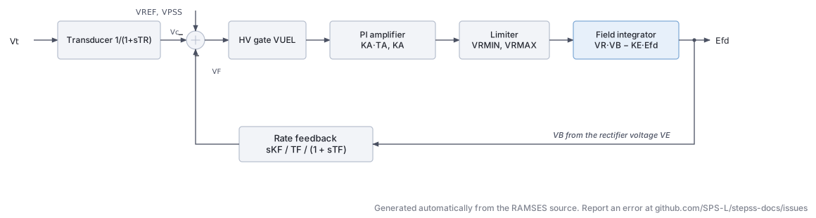
Section titled “ST2A (via EXPIC1)”The EXPIC1 model implements a static exciter with an AC rotating bus-fed rectifier and an integrating (PI-type) amplifier path: . The output is proportional to the AC voltage phasor magnitude, creating a bus-fed topology analogous to IEEE Type ST2A. When , the rectifier gain is unity.
Mathematical Description
Section titled “Mathematical Description”The AC exciter voltage and rectifier:
The integrating amplifier:
The field voltage integrator:
Signal Flow
Section titled “Signal Flow”- Voltage measurement (
tf1p): with - Summation (
algeq): - UEL gate (
max1v1c): clamped to - PI amplifier (
pictl): with and - Output limiter (
lim): - Rectifier voltage (
algeq): , - Field integrator (
inlim): from - Derivative feedback (
tfder1p):
Parameters
Section titled “Parameters”| Parameter | Description | Unit/Type |
|---|---|---|
Kvcomp | Voltage compensation gain | pu |
Rc | Line drop resistance | pu |
Xc | Line drop reactance | pu |
TR | Measurement time constant | s |
VUEL | UEL signal | pu |
KA | Amplifier gain | pu |
TA | Amplifier time constant | s |
VRMAX | Maximum regulator output | pu |
VRMIN | Minimum regulator output | pu |
KF | Rate feedback gain | pu |
TF | Rate feedback time constant | s |
KE | Exciter self-excitation constant | pu |
EFDMAX | Maximum field voltage | pu |
EFDMIN | Minimum field voltage | pu |
TE | Field integrator time constant | s |
KP | AC source voltage proportional factor | pu |
KI | AC source voltage quadrature factor | pu |
KC | Commutation voltage drop factor | pu |
Variants
Section titled “Variants”| Model | Description |
|---|---|
EXPIC1 | Base bus-fed static exciter |
EXPIC1_PSS2B | Adds PSS2B dual-input stabilizer |
EXPIC1_PSS2B_MAXEX2 | Adds PSS2B + MAXEX2 field current limiter |
Usage Example
Section titled “Usage Example”Show the data record
SYNC_MACH g1 g1 # FP FQ P Q: share of the power-flow injection (FP, FQ) or initial power (P in MW, Q in Mvar) 1. 1. 0. 0. # SNOM: Nominal apparent power, used as base power in the machine model (MVA) 800. # Pnom: Nominal active power of the turbine, used as base power for the turbine model (MW) 760. # H: Inertia constant (s) 3. # D: Damping coefficient (usually set to zero when the damper windings are modelled) (pu) 0. # IBRATIO: Field current base ratio I_fB^mac/I_fB^exc (see above) (pu) 0.95 # TYPE_MOD: Parameter format keyword: RL or XT (case-insensitive) XT # Xl: Leakage reactance L_l (pu) 0.15 # Xd: d-axis synchronous reactance (pu) 1.1 # X'd: d-axis transient reactance (must be smaller than Xd) (pu) 0.25 # X"d: d-axis subtransient reactance (pu) 0.2 # Xq: q-axis synchronous reactance (pu) 0.7 # X'q: q-axis transient reactance (pu) * # X"q: q-axis subtransient reactance (pu) 0.2 # m: Saturation coefficient (set to 0 to neglect saturation) 0.1 # n: Saturation exponent (ignored when m = 0) 6.0257 # Ra: Armature resistance (pu) 0. # T'do: d-axis open-circuit transient time constant (s) 5.00 # T"do: d-axis open-circuit subtransient time constant (s) 0.05 # T'qo: q-axis open-circuit transient time constant (s) * # T"qo: q-axis open-circuit subtransient time constant (s) 0.1EXC EXPIC1 # Kvcomp: weight of the terminal voltage in the measured voltage |Kv V + (Rc+jXc) I|; 1 = terminal voltage 1. # Rc: Compensation resistance (pu) 0. # Xc: Compensation reactance (pu) 0. # TR: Voltage measurement time constant (s) 0.02 # VUEL: UEL signal, lower bound of the voltage error (pu) -99999 # KA: PI amplifier integral gain, KA(1+sTA)/s (1/s) 200.0 # TA: PI amplifier time constant (s) 0.02 # VRMAX: Maximum regulator output (pu) 99.0 # VRMIN: Minimum regulator output (pu) -99.0 # KF: Rate feedback gain (pu) 0.0 # TF: Rate feedback time constant (s) 1.0 # KE: Exciter self-excitation constant (pu) 1.0 # EFDMAX: Maximum field voltage (pu) 8.0 # EFDMIN: Minimum field voltage (pu) -8.0 # TE: Field integrator time constant (s) 0.5 # KP: Potential source gain on terminal voltage (pu) 0.0 # KI: Current source gain on terminal current (pu) 1.0 # KC: Rectifier commutation factor (pu) 0.0TOR CONSTANT;IEEET5
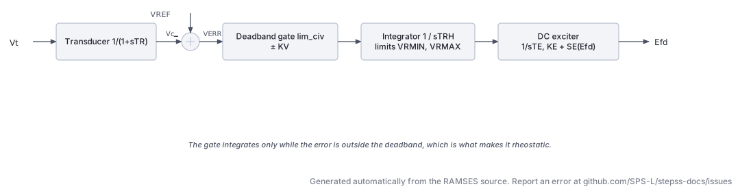
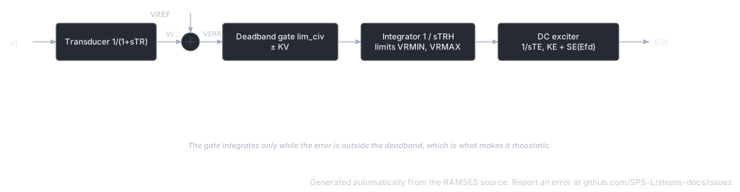
Section titled “IEEET5”The IEEET5 (also referenced as DC5A in some conventions) is a non-continuously acting exciter similar to DC3A but uses an inner limiter block lim_civ that gates the integrator holding signal within a deadband . This creates the three-state (hold/raise/lower) behavior of rheostatic controllers.
Mathematical Description
Section titled “Mathematical Description”
The integrator for rheostat position:
The lim_civ block implements the deadband gating so that integration is active only when :
Parameters
Section titled “Parameters”| Parameter | Description | Unit/Type |
|---|---|---|
Kvcomp | Voltage compensation gain | pu |
Rc | Line drop resistance | pu |
Xc | Line drop reactance | pu |
TRH | Rheostat time | s |
KV | Controller sensitivity deadband | pu |
VRMAX | Maximum field voltage | pu |
VRMIN | Minimum field voltage | pu |
TE | Exciter integrator time constant | s |
KE | Exciter self-excitation constant | pu |
E1 | Saturation point 1 | pu |
SE1 | Saturation factor at | pu |
E2 | Saturation point 2 | pu |
SE2 | Saturation factor at | pu |
Variants
Section titled “Variants”| Model | Description |
|---|---|
IEEET5 | Base model, non-continuously acting DC exciter |
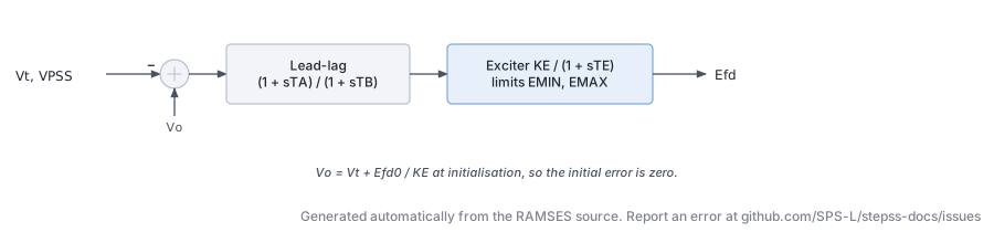
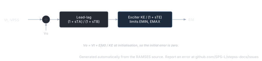
The SEXS (Simplified Excitation System) is a minimal two-parameter static exciter model from CIGRÉ publications, widely used for cases where detailed exciter data is unavailable. It has no measurement filter, no line drop compensation, and no rate feedback, just a lead-lag network and a limited first-order block.
Mathematical Description
Section titled “Mathematical Description”
where is computed from initial conditions to achieve zero initial error.
Parameters
Section titled “Parameters”| Parameter | Description | Unit/Type |
|---|---|---|
TA | Lead-lag numerator time constant | s |
TB | Lead-lag denominator time constant | s |
KE | Exciter gain | pu |
TE | Exciter time constant | s |
EMIN | Minimum field voltage | pu |
EMAX | Maximum field voltage | pu |
Variants
Section titled “Variants”| Model | Description |
|---|---|
SEXS | Base simplified exciter |
SEXS_IEEEST | Adds IEEEST PSS (multi-mode: speed, power, or accelerating power input) |
SEXS_STAB3_lim | Adds STAB3 PSS + integral OEL |
Usage Example
Section titled “Usage Example”Show the data record
SYNC_MACH g1 g1 # FP FQ P Q: share of the power-flow injection (FP, FQ) or initial power (P in MW, Q in Mvar) 1. 1. 0. 0. # SNOM: Nominal apparent power, used as base power in the machine model (MVA) 800. # Pnom: Nominal active power of the turbine, used as base power for the turbine model (MW) 760. # H: Inertia constant (s) 3. # D: Damping coefficient (usually set to zero when the damper windings are modelled) (pu) 0. # IBRATIO: Field current base ratio I_fB^mac/I_fB^exc (see above) (pu) 0.95 # TYPE_MOD: Parameter format keyword: RL or XT (case-insensitive) XT # Xl: Leakage reactance L_l (pu) 0.15 # Xd: d-axis synchronous reactance (pu) 1.1 # X'd: d-axis transient reactance (must be smaller than Xd) (pu) 0.25 # X"d: d-axis subtransient reactance (pu) 0.2 # Xq: q-axis synchronous reactance (pu) 0.7 # X'q: q-axis transient reactance (pu) * # X"q: q-axis subtransient reactance (pu) 0.2 # m: Saturation coefficient (set to 0 to neglect saturation) 0.1 # n: Saturation exponent (ignored when m = 0) 6.0257 # Ra: Armature resistance (pu) 0. # T'do: d-axis open-circuit transient time constant (s) 5.00 # T"do: d-axis open-circuit subtransient time constant (s) 0.05 # T'qo: q-axis open-circuit transient time constant (s) * # T"qo: q-axis open-circuit subtransient time constant (s) 0.1EXC SEXS # TA: Lead-lag numerator time constant 0.1 # TB: Lead-lag denominator time constant 10.0 # KE: Exciter gain 25.0 # TE: Exciter time constant 0.5 # EMIN: Minimum field voltage -5.0 # EMAX: Maximum field voltage 5.0TOR CONSTANT;ENTSOE_simp
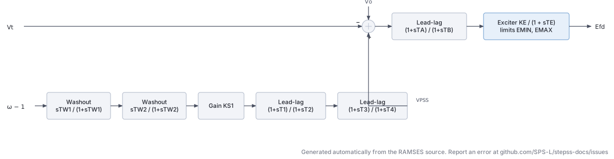
Section titled “ENTSOE_simp”The ENTSO-E simplified exciter combines a built-in speed-signal PSS with a simple lead-lag AVR and first-order exciter block. It is the standard ENTSO-E model for dynamic studies where detailed exciter data is unavailable.
Mathematical Description
Section titled “Mathematical Description”The PSS (speed input ) uses two washout stages and two lead-lag stages:
The AVR:
Parameters
Section titled “Parameters”| Parameter | Description | Unit/Type |
|---|---|---|
TW1 | First washout time constant | s |
TW2 | Second washout time constant | s |
KS1 | PSS gain | pu |
T1 | First lead-lag numerator | s |
T2 | First lead-lag denominator | s |
T3 | Second lead-lag numerator | s |
T4 | Second lead-lag denominator | s |
VSTMIN | PSS output lower limit | pu |
VSTMAX | PSS output upper limit | pu |
TA | AVR lead-lag numerator | s |
TB | AVR lead-lag denominator | s |
KE | Exciter gain | pu |
TE | Exciter time constant | s |
EMIN | Minimum field voltage | pu |
EMAX | Maximum field voltage | pu |
Variants
Section titled “Variants”| Model | Description |
|---|---|
ENTSOE_simp | Base ENTSO-E simplified model with integrated PSS |
ENTSOE_lim | Adds integral OEL (same structure as AC8B_lim OEL) |
Usage Example
Section titled “Usage Example”Show the data record
SYNC_MACH g1 g1 # FP FQ P Q: share of the power-flow injection (FP, FQ) or initial power (P in MW, Q in Mvar) 1. 1. 0. 0. # SNOM: Nominal apparent power, used as base power in the machine model (MVA) 800. # Pnom: Nominal active power of the turbine, used as base power for the turbine model (MW) 760. # H: Inertia constant (s) 3. # D: Damping coefficient (usually set to zero when the damper windings are modelled) (pu) 0. # IBRATIO: Field current base ratio I_fB^mac/I_fB^exc (see above) (pu) 0.95 # TYPE_MOD: Parameter format keyword: RL or XT (case-insensitive) XT # Xl: Leakage reactance L_l (pu) 0.15 # Xd: d-axis synchronous reactance (pu) 1.1 # X'd: d-axis transient reactance (must be smaller than Xd) (pu) 0.25 # X"d: d-axis subtransient reactance (pu) 0.2 # Xq: q-axis synchronous reactance (pu) 0.7 # X'q: q-axis transient reactance (pu) * # X"q: q-axis subtransient reactance (pu) 0.2 # m: Saturation coefficient (set to 0 to neglect saturation) 0.1 # n: Saturation exponent (ignored when m = 0) 6.0257 # Ra: Armature resistance (pu) 0. # T'do: d-axis open-circuit transient time constant (s) 5.00 # T"do: d-axis open-circuit subtransient time constant (s) 0.05 # T'qo: q-axis open-circuit transient time constant (s) * # T"qo: q-axis open-circuit subtransient time constant (s) 0.1EXC ENTSOE_simp # TW1: First PSS washout time constant (s) 10.0 # TW2: Second PSS washout time constant (s) 3.0 # KS1: PSS gain, applied in the first lead-lag (pu/pu) 10.0 # T1: PSS first lead-lag numerator time constant (s) 0.2 # T2: PSS first lead-lag denominator time constant (s) 0.1 # T3: PSS second lead-lag numerator time constant (s) 0.1 # T4: PSS second lead-lag denominator time constant (s) 0.1 # VSTMIN: PSS output lower limit (pu) -0.05 # VSTMAX: PSS output upper limit (pu) 0.05 # TA: AVR lead-lag numerator time constant (s) 0.05 # TB: AVR lead-lag denominator time constant (s) 0.1 # KE: Exciter gain (pu/pu) 25.0 # TE: Exciter time constant (s) 1.0 # EMIN: Minimum field voltage (pu) -10.0 # EMAX: Maximum field voltage (pu) 10.0TOR CONSTANT;