

Generic Exciters
Generic voltage regulators with optional stabilizer and limiter stages, and the regulator of a diesel generator. GENERIC1 and GENERIC2 are built in and written in uppercase with no prefix; GENERIC and AVR_DG are registered, and RAMSES adds the exc_ prefix automatically.
The EXC sub-record these models are entered with, and the table of IEEE model variants, are on the Exciter Models page.
GENERIC1 (exc_generic1)
Section titled “GENERIC1 (exc_generic1)”The data-file model name is GENERIC1.
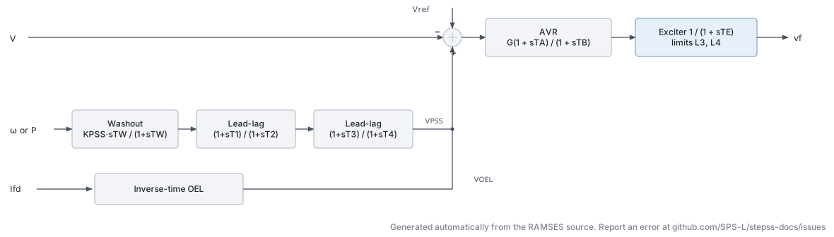
Scientific Description
Section titled “Scientific Description”The exc_generic1 model is a generic AVR with OEL (Over-Excitation Limiter) and PSS, implemented in Fortran. It includes a proportional–integral AVR, a PSS acting on rotor speed or active power, and an inverse-time OEL.
AVR:
The excitation system uses a first-order integrating controller (washout or PI-type, set by the gain and time constants , ) with output limits :
PSS (speed or power input, selectable):
Input signal is selected by SPEEDIN: 1 = rotor speed , 0 = electrical power .
Output is clamped to .
OEL (inverse-time limiter):
The OEL monitors field current . When , a timer begins accumulating via:
- Dead zone and phase parameters control OEL activation thresholds.
- The OEL integrates the overcurrent error and reduces once the timer reaches threshold , with output range .
Parameters from Fortran source (prm array):
| Index | Name | Description |
|---|---|---|
| 1 | IFLIM | Field current OEL threshold (pu) |
| 2 | d | OEL dead zone (pu) |
| 3 | f | OEL phase characteristic |
| 4 | S | AVR setpoint input (usually 0 = ) |
| 5 | K1 | AVR lead numerator gain |
| 6 | K2 | AVR lag denominator gain |
| 7 | L1 | OEL integrator lower limit (pu) |
| 8 | L2 | OEL integrator upper limit (pu) |
| 9 | G | AVR overall gain |
| 10 | TA | AVR lead time constant (s) |
| 11 | TB | AVR lag time constant (s) |
| 12 | TE | Exciter time constant (s) |
| 13 | L3 | AVR output lower limit (pu) |
| 14 | L4 | AVR output upper limit (pu) |
| 15 | SPEEDIN | PSS input signal: 1 = speed, 0 = power |
| 16 | KPSS | PSS gain |
| 17 | Tw | PSS washout time constant (s) |
| 18 | T1 | PSS lead–lag 1 zero (s) |
| 19 | T2 | PSS lead–lag 1 pole (s) |
| 20 | T3 | PSS lead–lag 2 zero (s) |
| 21 | T4 | PSS lead–lag 2 pole (s) |
| 22 | DVMIN | PSS output lower limit (pu) |
| 23 | DVMAX | PSS output upper limit (pu) |
Usage Example
Section titled “Usage Example”Show the data record
SYNC_MACH GEN1 BUS1 # FP FQ P Q: share of the power-flow injection (FP, FQ) or initial power (P in MW, Q in Mvar) 1. 1. 0. 0. # SNOM: Nominal apparent power, used as base power in the machine model (MVA) 600. # Pnom: Nominal active power of the turbine, used as base power for the turbine model (MW) 570. # H: Inertia constant (s) 3. # D: Damping coefficient (usually set to zero when the damper windings are modelled) (pu) 0. # IBRATIO: Field current base ratio I_fB^mac/I_fB^exc (see above) (pu) 0.95 # TYPE_MOD: Parameter format keyword: RL or XT (case-insensitive) XT # Xl: Leakage reactance L_l (pu) 0.15 # Xd: d-axis synchronous reactance (pu) 1.1 # X'd: d-axis transient reactance (must be smaller than Xd) (pu) 0.25 # X"d: d-axis subtransient reactance (pu) 0.2 # Xq: q-axis synchronous reactance (pu) 0.7 # X'q: q-axis transient reactance (pu) * # X"q: q-axis subtransient reactance (pu) 0.2 # m: Saturation coefficient (set to 0 to neglect saturation) 0.1 # n: Saturation exponent (ignored when m = 0) 6.0257 # Ra: Armature resistance (pu) 0. # T'do: d-axis open-circuit transient time constant (s) 5.00 # T"do: d-axis open-circuit subtransient time constant (s) 0.05 # T'qo: q-axis open-circuit transient time constant (s) * # T"qo: q-axis open-circuit subtransient time constant (s) 0.1EXC GENERIC1 # IFLIM: OEL field current threshold (pu) 1.05 # d: OEL timer band, usually negative: timer runs down at rate 1 below IFLIM+d, holds between IFLIM+d and IFLIM (pu) -0.1 # f: OEL timer charging rate offset above IFLIM 0.5 # S: OEL timer charging rate per unit of field overcurrent (1/pu) 0.0 # K1: Not used by the code 1.0 # K2: OEL gain on (if - IFLIM), negative so that the OEL lowers excitation (pu/pu) -1.0 # L1: OEL timer lower limit and initial value, negative; the OEL acts when the timer exceeds 0 (s) -20. # L2: OEL timer upper limit (s) 0.5 # G: AVR gain (pu/pu) 200.0 # TA: AVR lead time constant (s) 0.02 # TB: AVR lag time constant (s) 0.10 # TE: Exciter time constant (s) 0.05 # L3: Minimum field voltage (pu) 0.0 # L4: Maximum field voltage (pu) 6.0 # SPEEDIN: PSS input weight: 1 = speed, 0 = active power 1 # KPSS: PSS gain, derivative washout KPSS s/(1+sTw); 0 disables PSS (pu s) 9.5 # Tw: PSS washout time constant (s) 1.40 # T1: PSS first lead-lag numerator time constant (s) 0.15 # T2: PSS first lead-lag denominator time constant (s) 0.03 # T3: PSS second lead-lag numerator time constant (s) 0.15 # T4: PSS second lead-lag denominator time constant (s) 0.03 # DVMIN: PSS output lower limit (pu) -0.10 # DVMAX: PSS output upper limit (pu) 0.10TOR CONSTANT;AVR_DG (exc_AVR_DG)
Section titled “AVR_DG (exc_AVR_DG)”The data-file model name is AVR_DG. Registered since 3.76.
Scientific Description
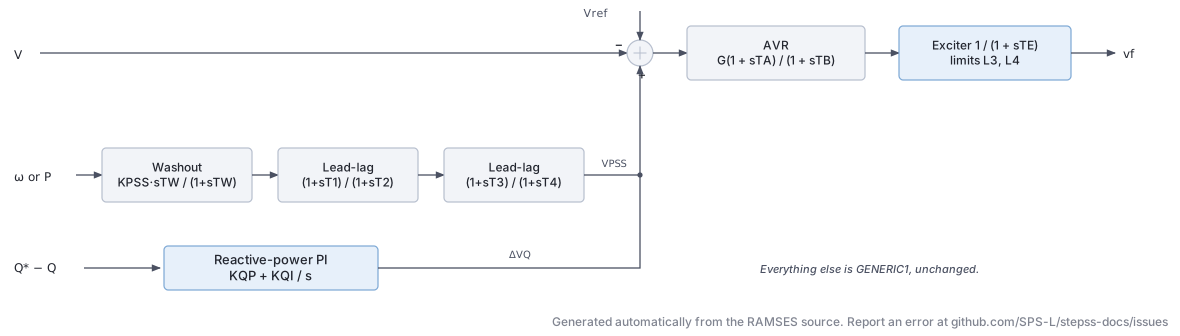
Section titled “Scientific Description”An AVR for dispersed generation: the GENERIC1 excitation
system, OEL and PSS, plus a reactive-power PI controller that trims the voltage
reference so the unit holds a reactive-power setpoint.
Parameters 1 to 23 are those of GENERIC1, in the same positions and with the same
meanings, and the AVR, PSS and OEL behave identically. Only the summing junction changes,
gaining a third contribution:
Reactive-power regulator:
The error is the deviation from the setpoint captured at initialisation:
clamped to . Setting leaves the loop dormant and the
model reduces to GENERIC1.
Parameters:
Indices 1 to 23 are exactly those of GENERIC1. The four that
follow are new:
| Index | Name | Description |
|---|---|---|
| 24 | KQP | Reactive-power regulator proportional gain |
| 25 | KQI | Reactive-power regulator integral gain |
| 26 | L5 | Regulator output lower limit (pu) |
| 27 | L6 | Regulator output upper limit (pu) |
Implementation details:
nbxvar = 8,nbzvar = 7,nbdata = 27,nbaddpar = 2- Additional:
prm(28) = V0(voltage reference) andprm(29) = Qset, both captured at initialisation - Observables: those of
GENERIC1plusdeltavqandQset
Usage Example
Section titled “Usage Example”Show the data record
SYNC_MACH G4 N4 # FP FQ P Q: share of the power-flow injection (FP, FQ) or initial power (P in MW, Q in Mvar) 1. 1. 0. 0. # SNOM: Nominal apparent power, used as base power in the machine model (MVA) 5 # Pnom: Nominal active power of the turbine, used as base power for the turbine model (MW) 4.5 # H: Inertia constant (s) 3. # D: Damping coefficient (usually set to zero when the damper windings are modelled) (pu) 0. # IBRATIO: Field current base ratio I_fB^mac/I_fB^exc (see above) (pu) 1.9333 # TYPE_MOD: Parameter format keyword: RL or XT (case-insensitive) XT # Xl: Leakage reactance L_l (pu) 0.0937 # Xd: d-axis synchronous reactance (pu) 2.027 # X'd: d-axis transient reactance (must be smaller than Xd) (pu) 0.210 # X"d: d-axis subtransient reactance (pu) 0.173 # Xq: q-axis synchronous reactance (pu) 2.027 # X'q: q-axis transient reactance (pu) * # X"q: q-axis subtransient reactance (pu) 0.173 # m: Saturation coefficient (set to 0 to neglect saturation) 0.1 # n: Saturation exponent (ignored when m = 0) 6 # Ra: Armature resistance (pu) 0.00 # T'do: d-axis open-circuit transient time constant (s) 3.1 # T"do: d-axis open-circuit subtransient time constant (s) 0.0387 # T'qo: q-axis open-circuit transient time constant (s) * # T"qo: q-axis open-circuit subtransient time constant (s) 0.0387EXC AVR_DG # IFLIM: OEL field current threshold (pu) 2.865 # d: OEL timer band, usually negative: timer runs down at rate 1 below IFLIM+d, holds between IFLIM+d and IFLIM (pu) -0.1 # f: OEL timer charging rate offset above IFLIM 0. # S: OEL timer charging rate per unit of field overcurrent (1/pu) 1. # K1: Not used by the code 100. # K2: OEL gain on field current error if minus IFLIM (pu/pu) -1. # L1: OEL timer lower limit (initial value) (s) -20 # L2: OEL timer upper limit (s) 10 # G: AVR gain (pu/pu) 50 # TA: AVR lead time constant (s) 4 # TB: AVR lag time constant (s) 20 # TE: Exciter time constant (s) 0.1 # L3: Minimum field voltage (pu) 0 # L4: Maximum field voltage (pu) 5 # SPEEDIN: PSS input weight: 1 = speed, 0 = active power 1 # KPSS: PSS gain, derivative washout KPSS s/(1+sTw); 0 disables PSS (pu s) 0. # Tw: PSS washout time constant (s) 5. # T1: PSS first lead-lag numerator time constant (s) 1. # T2: PSS first lead-lag denominator time constant (s) 1. # T3: PSS second lead-lag numerator time constant (s) 1. # T4: PSS second lead-lag denominator time constant (s) 1. # DVMIN: PSS output lower limit (pu) 0. # DVMAX: PSS output upper limit (pu) 0. # KQP: Reactive power regulator proportional gain (pu/pu) 0.04 # KQI: Reactive power regulator integral gain (1/s) 0.06 # L5: Reactive power regulator output lower limit (pu) -0.2 # L6: Reactive power regulator output upper limit (pu) 0.33TOR HYDRO_DG # Qv: no-load water flow (pu) 0.0 # Kp: PI proportional gain on power error 0.1 # Ki: PI integral gain on power error (1/s) 0.4 # TSM: gate servomotor time constant (s) 0.2 # LIMZDOT: gate velocity limit, applied as plus or minus (pu/s) 0.1 # TW: water starting time (s) 1.0;- The setpoint is not a parameter.
Qsetis captured from the power-flow solution at initialisation, so the unit holds whatever reactive power it was dispatched at. - With
KQPandKQInon-zero the unit regulates reactive power rather than terminal voltage, which is the usual arrangement for dispersed generation connected to a distribution network under a connection agreement. KPSS = 0disables the stabiliser. Note that this drives the PSS branch to its lower limit, soDVMINshould be 0 as well, as in the example above.- Pair it with
HYDRO_DGfor a unit that regulates both its active and reactive power and provides no primary frequency response.
GENERIC2 (exc_generic2)
Section titled “GENERIC2 (exc_generic2)”The data-file model name is GENERIC2.
Scientific Description
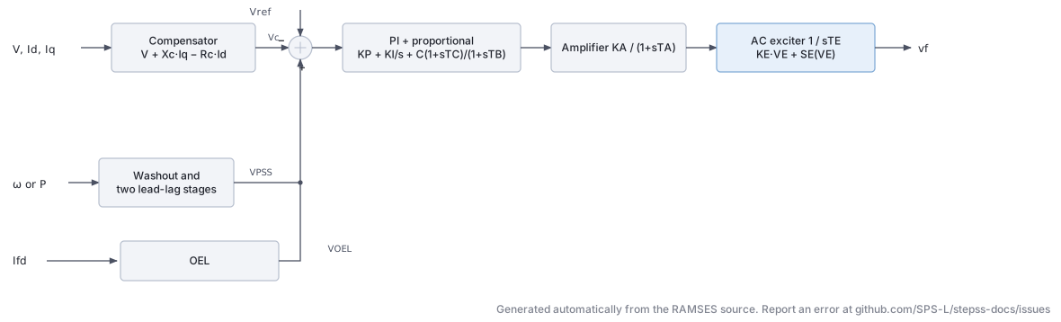
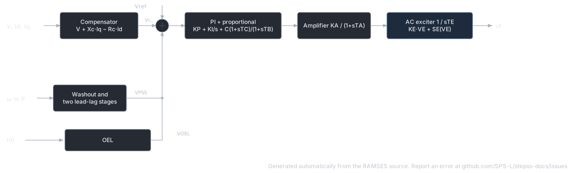
Section titled “Scientific Description”The exc_generic2 model is a more detailed generic AVR. It includes a voltage compensator, a combined PI–proportional regulator, an AC exciter with saturation, a PSS, and an OEL.
Voltage measurement with line-drop compensation:
PI–proportional AVR with transient gain reduction:
AC exciter with saturation:
where is the piecewise-linear saturation function defined by and .
PSS (type selectable by typss):
OEL (inverse-time, three-segment):
The OEL uses a three-level piecewise-linear characteristic , , to compute the allowable overcurrent time.
Parameters from Fortran associate block (39 data parameters + 4 additional):
| Index | Name | Description |
|---|---|---|
| 1 | Xc | Line-drop compensation reactance (pu) |
| 2 | Tr | Voltage measurement time constant (s) |
| 3 | C | TGR numerator gain |
| 4 | Tc | TGR lead time constant (s) |
| 5 | Tb | TGR lag time constant (s) |
| 6 | Ka | AVR proportional gain |
| 7 | Ta | AVR time constant (s) |
| 8 | Ki | AVR integral gain |
| 9 | Kp | AVR proportional path gain |
| 10 | VrmaxD | Regulator max (dynamic, pu) |
| 11 | VrminD | Regulator min (dynamic, pu) |
| 12 | G | Exciter overall gain |
| 13 | Ke | Exciter self-excitation coefficient |
| 14 | Te | Exciter time constant (s) |
| 15 | E1 | Saturation breakpoint 1 (pu) |
| 16 | SeE1 | Saturation factor at |
| 17 | E2 | Saturation breakpoint 2 (pu) |
| 18 | SeE2 | Saturation factor at |
| 19 | Vrmax | Field voltage upper limit (pu) |
| 20 | Vrmin | Field voltage lower limit (pu) |
| 21 | typss | PSS input type (1 = speed, 2 = power) |
| 22 | W | PSS input gain |
| 23 | Tf | PSS derivative filter time constant (s) |
| 24 | Kpss | PSS gain |
| 25 | Tw | PSS washout time constant (s) |
| 26 | T1 | PSS lead–lag 1 zero (s) |
| 27 | T2 | PSS lead–lag 1 pole (s) |
| 28 | T3 | PSS lead–lag 2 zero (s) |
| 29 | T4 | PSS lead–lag 2 pole (s) |
| 30 | Lim | PSS output symmetric limit (pu) |
| 31 | LimSup | PSS upper asymmetric limit (pu) |
| 32 | s1 | OEL segment 1 (pu ) |
| 33 | toel1 | OEL time at segment 1 (s) |
| 34 | s2 | OEL segment 2 (pu ) |
| 35 | toel2 | OEL time at segment 2 (s) |
| 36 | s3 | OEL segment 3 (pu ) |
| 37 | toel3 | OEL time at segment 3 (s) |
| 38 | perm | OEL permanent current limit (pu) |
| 39 | LimInf | PSS lower asymmetric limit (pu) |
Usage Example
Section titled “Usage Example”Show the data record
SYNC_MACH GEN1 BUS1 # FP FQ P Q: share of the power-flow injection (FP, FQ) or initial power (P in MW, Q in Mvar) 1. 1. 0. 0. # SNOM: Nominal apparent power, used as base power in the machine model (MVA) 600. # Pnom: Nominal active power of the turbine, used as base power for the turbine model (MW) 570. # H: Inertia constant (s) 3. # D: Damping coefficient (usually set to zero when the damper windings are modelled) (pu) 0. # IBRATIO: Field current base ratio I_fB^mac/I_fB^exc (see above) (pu) 0.95 # TYPE_MOD: Parameter format keyword: RL or XT (case-insensitive) XT # Xl: Leakage reactance L_l (pu) 0.15 # Xd: d-axis synchronous reactance (pu) 1.1 # X'd: d-axis transient reactance (must be smaller than Xd) (pu) 0.25 # X"d: d-axis subtransient reactance (pu) 0.2 # Xq: q-axis synchronous reactance (pu) 0.7 # X'q: q-axis transient reactance (pu) * # X"q: q-axis subtransient reactance (pu) 0.2 # m: Saturation coefficient (set to 0 to neglect saturation) 0.1 # n: Saturation exponent (ignored when m = 0) 6.0257 # Ra: Armature resistance (pu) 0. # T'do: d-axis open-circuit transient time constant (s) 5.00 # T"do: d-axis open-circuit subtransient time constant (s) 0.05 # T'qo: q-axis open-circuit transient time constant (s) * # T"qo: q-axis open-circuit subtransient time constant (s) 0.1EXC GENERIC2 # Xc: Compensation reactance (pu) 0.0 # Tr: Voltage measurement time constant, 0 = algebraic (s) 0.02 # C: Forward path selector: 0 = PI (Ki, Kp), 1 = lead-lag (Tc, Tb) 1.0 # Tc: Lead-lag numerator time constant, used when C = 1 (s) 0.10 # Tb: Lead-lag denominator time constant, used when C = 1 (s) 1.00 # Ka: Amplifier gain (pu/pu) 200.0 # Ta: Amplifier time constant, 0 = algebraic (s) 0.05 # Ki: PI integral gain, used when C = 0 (1/s) 5.0 # Kp: PI proportional gain, used when C = 0 (pu/pu) 1.0 # VrmaxD: Amplifier output upper limit (pu) 6.0 # VrminD: Amplifier output lower limit (pu) -6.0 # G: Exciter selector: 1 = static (vf from amplifier), 0 = rotating exciter 1.0 # Ke: Exciter self-excitation constant (pu) 1.0 # Te: Exciter time constant (s) 0.50 # E1: First saturation point field voltage (pu) 3.10 # SeE1: Saturation factor at E1 0.066 # E2: Second saturation point field voltage (pu) 4.18 # SeE2: Saturation factor at E2 0.91 # Vrmax: Field voltage upper limit, multiplied by terminal voltage (pu) 6.0 # Vrmin: Field voltage lower limit, multiplied by terminal voltage (pu) -6.0 # typss: PSS input: 0 = none, 1 = speed deviation, 2 = active power, 3 = filtered speed derivative 1.0 # W: PSS washout switch: 1 = washout, otherwise pure gain 1.0 # Tf: Speed derivative filter time constant, used when typss = 3 (s) 0.05 # Kpss: PSS gain; with W = 1 the washout is Kpss s/(1+sTw) and Kpss must be nonzero 9.5 # Tw: PSS washout time constant (s) 1.40 # T1: PSS first lead-lag numerator time constant (s) 0.154 # T2: PSS first lead-lag denominator time constant (s) 0.033 # T3: PSS second lead-lag numerator time constant (s) 0.154 # T4: PSS second lead-lag denominator time constant (s) 0.033 # Lim: PSS output symmetric limit (pu) 0.10 # LimSup: OEL field current above which the OEL acts without delay; highest threshold (pu) 2.0 # s1: OEL upper threshold, below LimSup (pu) 1.5 # toel1: OEL delay for field current between s1 and LimSup (s) 10. # s2: OEL middle threshold, below s1 (pu) 1.2 # toel2: OEL delay for field current between s2 and s1 (s) 60. # s3: OEL pickup, the lowest threshold; the timer starts above it (pu) 1.1 # toel3: OEL delay for field current between s3 and s2 (s) 200. # perm: Field voltage ceiling applied once the OEL has acted (pu) 1.05 # LimInf: Field current below which field voltage is floored at LimInf (pu) -0.10TOR CONSTANT;GENERIC (exc_GENERIC)
Section titled “GENERIC (exc_GENERIC)”The data-file model name is exc_GENERIC (or GENERIC. The exc_ prefix is added automatically).
Scientific Description
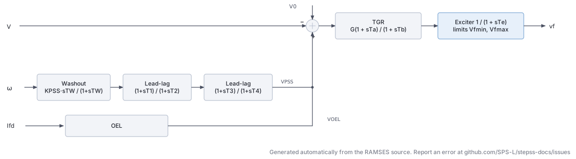
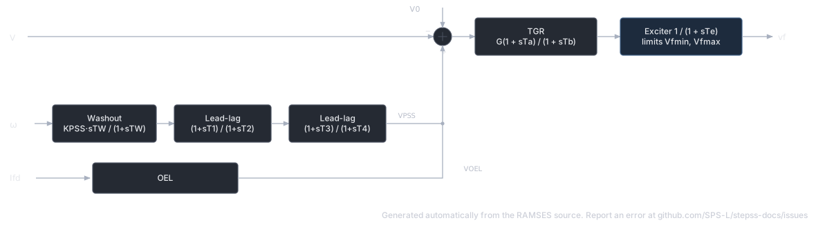
Section titled “Scientific Description”The exc_GENERIC model (note capital letters) is a generic AVR with integrated PSS and OEL, defined via the CODEGEN .txt description. It provides a clean, modular three-block structure: AVR, PSS, and OEL.
AVR (transient gain reduction + exciter):
where is computed at initialisation.
PSS (washout + two lead–lag stages):
Output is limited to .
OEL (inverse-time integrator):
The CODEGEN block structure from the .txt file:
| Block | CODEGEN type | Signal |
|---|---|---|
| AVR summing junction | algeq | |
| Transient gain reduction | tf1p1z | |
| Exciter | tf1plim | with |
| PSS washout | tfder1p | |
| PSS lead–lag 1 | tf1p1z | |
| PSS lead–lag 2 | tf1p1z | |
| PSS limiter | lim | |
| OEL error | algeq | |
| OEL upper bound | min1v1c | |
| OEL integrator | inlim | with |
| OEL multiplier | algeq | |
| OEL output limiter | lim |
Parameters
Section titled “Parameters”| Parameter | Description |
|---|---|
G | AVR gain (pu/pu) |
Ta | AVR lead time constant / TGR zero (s) |
Tb | AVR lag time constant / TGR pole (s) |
Te | Exciter time constant (s) |
vfmin | Minimum field voltage (pu) |
vfmax | Maximum field voltage (pu) |
Kpss | PSS gain |
Tw | PSS washout time constant (s) |
T1 | PSS first lead–lag zero (s) |
T2 | PSS first lead–lag pole (s) |
T3 | PSS second lead–lag zero (s) |
T4 | PSS second lead–lag pole (s) |
C | PSS output symmetric limit (pu) |
if1lim | OEL field current threshold (pu) |
if2lim | OEL maximum overcurrent error (pu) |
Toel | OEL integrator time constant (s) |
Koel | OEL output gain |
L1 | OEL integrator lower limit |
L2 | OEL integrator upper limit |
L3 | OEL output upper limit (pu) |
Computed at initialisation: Vo = V + Vf / G
Usage Example
Section titled “Usage Example”Show the data record
SYNC_MACH GEN1 BUS1 # FP FQ P Q: share of the power-flow injection (FP, FQ) or initial power (P in MW, Q in Mvar) 1. 1. 0. 0. # SNOM: Nominal apparent power, used as base power in the machine model (MVA) 600. # Pnom: Nominal active power of the turbine, used as base power for the turbine model (MW) 570. # H: Inertia constant (s) 3. # D: Damping coefficient (usually set to zero when the damper windings are modelled) (pu) 0. # IBRATIO: Field current base ratio I_fB^mac/I_fB^exc (see above) (pu) 0.95 # TYPE_MOD: Parameter format keyword: RL or XT (case-insensitive) XT # Xl: Leakage reactance L_l (pu) 0.15 # Xd: d-axis synchronous reactance (pu) 1.1 # X'd: d-axis transient reactance (must be smaller than Xd) (pu) 0.25 # X"d: d-axis subtransient reactance (pu) 0.2 # Xq: q-axis synchronous reactance (pu) 0.7 # X'q: q-axis transient reactance (pu) * # X"q: q-axis subtransient reactance (pu) 0.2 # m: Saturation coefficient (set to 0 to neglect saturation) 0.1 # n: Saturation exponent (ignored when m = 0) 6.0257 # Ra: Armature resistance (pu) 0. # T'do: d-axis open-circuit transient time constant (s) 5.00 # T"do: d-axis open-circuit subtransient time constant (s) 0.05 # T'qo: q-axis open-circuit transient time constant (s) * # T"qo: q-axis open-circuit subtransient time constant (s) 0.1EXC exc_GENERIC # G: AVR gain (pu/pu) 200.0 # Ta: Transient gain reduction lead time constant (s) 0.05 # Tb: Transient gain reduction lag time constant (s) 10.0 # Te: Exciter time constant (s) 0.04 # vfmin: Minimum field voltage (pu) 0.0 # vfmax: Maximum field voltage (pu) 5.0 # Kpss: PSS gain, washout Kpss s/(1+sTw) on speed (pu s) 9.5 # Tw: PSS washout time constant (s) 1.40 # T1: PSS first lead-lag numerator time constant (s) 0.154 # T2: PSS first lead-lag denominator time constant (s) 0.033 # T3: PSS second lead-lag numerator time constant (s) 0.154 # T4: PSS second lead-lag denominator time constant (s) 0.033 # C: PSS output symmetric limit (pu) 0.10 # if1lim: OEL field current threshold (pu) 1.05 # if2lim: OEL maximum overcurrent integrated (pu) 0.30 # Toel: OEL integrator time constant (s) 30.0 # Koel: OEL output gain (pu/pu) 1.0 # L1: OEL integrator lower limit (initial value) 0.0 # L2: OEL integrator upper limit 1.0 # L3: OEL output upper limit (pu) 2.0TOR CONSTANT;